LG GR-J303TS Service Manual - Page 26
Sensor Resistance Characteristics Table
 |
View all LG GR-J303TS manuals
Add to My Manuals
Save this manual to your list of manuals |
Page 26 highlights
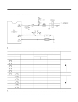
3-3. SENSOR RESISTANCE CHARACTERISTICS TABLE Measuring Temperature(°C) -20 °C -15 °C -10 °C -5 °C 0 °C +5 °C +10 °C +15 °C ` +20 °C +25 °C +30 °C +40 °C +50 °C Upper/Middle/Lower sensors, RT sensor, Upper/Middle defrosting sensors 77 KΩ 60 KΩ 47.3 KΩ 38.4 KΩ 30 KΩ 24.1 KΩ 19.5 KΩ 15.9 KΩ 13 KΩ 11 KΩ 8.9 KΩ 6.2 KΩ 4.3 KΩ (LCD MODULE:6871JB1464) (LED MODULE:6871JB1465) (Ambient temperature sensor) (UPPER SENSOR) (MIDDLE SENSOR) (LOWER SENSOR) (UPPER DEFROSTING SENSOR) (MIDDLE DEFROSTING SENSOR) u Allowance of sensor resistance is 3%. u Measure resistance value of sensor after leaving it for more than 3 minutes (delay is required due to sensing speed). u Always use a digital tester! Analog testers have too great a margin of error. u Measure resistance after separating PWB (PCB) assembly, the CON6 on the main part since the upper compartment sensor and the middle compartment sensor have no connector. Measure resistance at both ends of No.6, 7 of the CON5 for the RT-sensor. However, measure resistance at both ends of the sensor after separating barrier assembly between the middle compartment and the lower compartment for the lower compartment sensor. - 26 -
-
 1
1 -
2
-
3
-
4
-
5
-
6
-
7
-
8
-
9
-
10
-
11
-
12
-
13
-
14
-
15
-
16
-
17
-
18
-
19
-
20
-
 21
21 -
 22
22 -
 23
23 -
 24
24 -
 25
25 -
 26
26 -
 27
27 -
 28
28 -
 29
29 -
 30
30 -
 31
31 -
32
-
33
-
34
-
35
-
36
-
37
-
38
-
39
-
40
-
41
-
42
-
43
-
44
-
45
-
46
 |
 |
