LG GR-J303TS Service Manual - Page 25
MAIN MICOM, MICOM for, LED Control, DC 12V
 |
View all LG GR-J303TS manuals
Add to My Manuals
Save this manual to your list of manuals |
Page 25 highlights
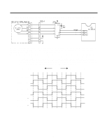
3-2-11. COMMUNICATION CIRCUIT BETWEEN MAIN PCB AND DISPLAY PCB Following circuits as communication circuits are circuits for changing necessary information between the main MICOM of the main PCB and the MICOM for LED control of the display PCB. DC12V for driving the display PCB, transmit/receive circuits are required. Poor communication occurs where continuing information change between the main MICOM of the main PCB and the MICOM for LED control of the display PCB is not done for more than 30 seconds. MAIN PCB DISPLAY PCB MAIN MICOM DC 12V GND Transmit (error status) Receive (notch status) MICOM for LED Control - 25 -
-
 1
1 -
2
-
3
-
4
-
5
-
6
-
7
-
8
-
9
-
10
-
11
-
12
-
13
-
14
-
15
-
16
-
17
-
18
-
19
-
 20
20 -
 21
21 -
 22
22 -
 23
23 -
 24
24 -
 25
25 -
 26
26 -
 27
27 -
 28
28 -
 29
29 -
 30
30 -
31
-
32
-
33
-
34
-
35
-
36
-
37
-
38
-
39
-
40
-
41
-
42
-
43
-
44
-
45
-
46
 |
 |

3-2-11. COMMUNICATION CIRCUIT BETWEEN MAIN PCB AND DISPLAY PCB
Following circuits as communication circuits are circuits for changing necessary information between the main MICOM of
the main PCB and the MICOM for LED control of the display PCB.
DC12V for driving the display PCB, transmit/receive circuits are required.
Poor communication occurs where continuing information change between the main MICOM of the main PCB and the
MICOM for LED control of the display PCB is not done for more than 30 seconds.
- 25 -
MAIN MICOM
MICOM for
LED Control
DC 12V
GND
Transmit (error status)
Receive (notch status)