Lenovo H430 Lenovo H4 Series Hardware Maintenance Manual V2.0
Lenovo H430 Manual
 |
View all Lenovo H430 manuals
Add to My Manuals
Save this manual to your list of manuals |
Lenovo H430 manual content summary:
- Lenovo H430 | Lenovo H4 Series Hardware Maintenance Manual V2.0 - Page 1
inspection guide 7 Handling electrostatic discharge-sensitive devices 8 Grounding requirements 8 Safety notices...9 Chapter 3. General information 12 Specifications...12 Chapter 4. General Checkout 13 Problem determination tips 14 Chapter 5. Using the Setup Utility (Type G41 16 Starting the - Lenovo H430 | Lenovo H4 Series Hardware Maintenance Manual V2.0 - Page 2
28 Hard disk drive boot error 28 Power Supply Problems 29 Beep symptoms 30 POST error codes 31 Undetermined problems 33 Chapter 8. Locations 34 Locating components 34 Locating connectors on the front of the computer 35 Locating connectors on the rear of the computer 36 Identifying parts on - Lenovo H430 | Lenovo H4 Series Hardware Maintenance Manual V2.0 - Page 3
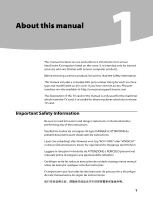
service and reference information for Lenovo IdeaCentre K computers listed on the cover. It is intended only for trained servicers who are familiar with Lenovo computer products. Before servicing a Lenovo product, be sure to read the Safety Information. This manual includes a complete FRU part - Lenovo H430 | Lenovo H4 Series Hardware Maintenance Manual V2.0 - Page 4
Manual Using eSupport For Key Commodities (Examples - hard disk drive, system board, microprocessor, LCD, and memory) •• eSupport can be used to view the list of key commodities built in a particular machine serial. •• eSupport can be accessed at the following Web site: http://www.lenovo.com/support - Lenovo H430 | Lenovo H4 Series Hardware Maintenance Manual V2.0 - Page 5
to support Lenovo's requirements and schedule. Products sold in 2005, will contain some RoHS compliant FRUs. The following statement pertains to these products and any product Lenovo produces containing RoHS compliant parts. RoHS compliant Lenovo IdeaCentre K parts have unique FRU part numbers - Lenovo H430 | Lenovo H4 Series Hardware Maintenance Manual V2.0 - Page 6
Manual Safety information 2 This chapter contains the safety information that you need to be familiar with before servicing a computer start the machine, ensure that other service representatives and the customer's personnel are not in a hazardous position. •• Place removed covers and other parts - Lenovo H430 | Lenovo H4 Series Hardware Maintenance Manual V2.0 - Page 7
be hazardous to your eyes. •• After service, reinstall all safety shields, guards, labels, power supplies - Removing or installing main units •• Before you start to work on the machine, unplug the power cord. If you cannot unplug it, ask the customer to power-off the wall box that supplies power - Lenovo H430 | Lenovo H4 Series Hardware Maintenance Manual V2.0 - Page 8
safety precautions when you work with very high voltages; these instructions are in the safety sections of maintenance information. Use extreme •• Do not service the following parts with the power on when they are removed from their normal operating places in a machine: - Power supply units - Pumps - Lenovo H430 | Lenovo H4 Series Hardware Maintenance Manual V2.0 - Page 9
safety items installed to protect users and service personnel from injury. This guide addresses only 2. Power-off the computer. Disconnect the power cord. 3. Check the power cord for: a. A third-wire ground connector in that the power-supply cover fasteners (screws or rivets) have not been removed or - Lenovo H430 | Lenovo H4 Series Hardware Maintenance Manual V2.0 - Page 10
Manual Handling electrostatic discharge-sensitive devices Any computer part that meets the specific service requirement. Note: connector-outside shells on these systems. - Use the round ground-prong of the ac plug on ac-operated computers. Grounding requirements Electrical grounding of the computer - Lenovo H430 | Lenovo H4 Series Hardware Maintenance Manual V2.0 - Page 11
is evidence of fire, water, or structural damage. •• Disconnect the attached power cords, telecommunications systems, networks, and modems before you open the device covers, unless instructed otherwise in the installation and configuration procedures. •• Connect and disconnect cables as described in - Lenovo H430 | Lenovo H4 Series Hardware Maintenance Manual V2.0 - Page 12
products (such as CD-ROMs, DVD-ROM drives, fiber optic devices, or transmitters) are installed, note the following: •• Do not remove the covers. Removing the covers of the laser product could result in exposure to hazardous laser radiation. There are no serviceable parts inside the device. •• Use - Lenovo H430 | Lenovo H4 Series Hardware Maintenance Manual V2.0 - Page 13
CAUTION: Use safe practices when lifting. CAUTION: The power control button on the device and the power switch on the power supply do not turn off the electrical current supplied to the device. The device also might have more than one power cord. To remove all electrical current from the device - Lenovo H430 | Lenovo H4 Series Hardware Maintenance Manual V2.0 - Page 14
Maintenance Manual General information 3 This chapter provides general information that applies to all machine types supported by this publication. Specifications This section lists the physical specifications for your computer. Type Lenovo H4 Series This section lists the physical specifications - Lenovo H430 | Lenovo H4 Series Hardware Maintenance Manual V2.0 - Page 15
this computer to boot up in quiet mode (no beep, no memory count and checkpoint code display) when no errors are detected by POST. • To enable beep, memory count, and checkpoint code display when a successful POST occurs, do the following: 1. Start the Setup Utility program. See "Starting the Setup - Lenovo H430 | Lenovo H4 Series Hardware Maintenance Manual V2.0 - Page 16
Hardware Maintenance Manual 5. Power-on the computer. • Look for displayed error codes • Listen for beep codes • Look for readable instructions or a main menu on the display. If you did not receive the correct response, proceed to step 6. If you do receive the correct response, proceed to step 7. 6. - Lenovo H430 | Lenovo H4 Series Hardware Maintenance Manual V2.0 - Page 17
Chapter 4. General Checkout Comparing the configuration and software set-up between "working and non-working" systems will often lead to problem resolution. 15 - Lenovo H430 | Lenovo H4 Series Hardware Maintenance Manual V2.0 - Page 18
the F1 key rather than leaving it pressed when turning on the computer. b. If a user password or an supervisor password has been set, the Setup Utility program menu is not displayed until you type your password. For more information, see "Using passwords." The Setup Utility might start automatically - Lenovo H430 | Lenovo H4 Series Hardware Maintenance Manual V2.0 - Page 19
access to your computer and data. See "Starting the Setup Utility program." The following types of passwords are available: • Supervisor Password • User character. • Setup Utility program and hard disk drive passwords are not case sensitive • Not be your name or your user name • Not be a common word - Lenovo H430 | Lenovo H4 Series Hardware Maintenance Manual V2.0 - Page 20
that Enter New Password. Press Enter and a message will display that indicates the password has been disabled. After that, the user password will be disabled too if a user password has been installed. 3. Press any key to contine. User Password When a User Password is set, you cannot start the - Lenovo H430 | Lenovo H4 Series Hardware Maintenance Manual V2.0 - Page 21
message will display that Enter New Password. Press Enter and a message will display that indicates the password has been disabled. 3. Press any key to contine. Using Device Device is used to enable or disable user access to the following device: PS/2 Mouse Support When this feature is - Lenovo H430 | Lenovo H4 Series Hardware Maintenance Manual V2.0 - Page 22
from any boot device. Note: Not all CDs, hard disks, and diskettes are bootable. 1. Turn off your computer. 2. Press and hold the F12 key then turn on the computer. When the Startup Device Menu appears, release the F12 key. Note: If you are using a USB keyboard and the Startup Device Menu does not - Lenovo H430 | Lenovo H4 Series Hardware Maintenance Manual V2.0 - Page 23
the Setup Utility Exiting from the Setup Utility program When you finish viewing or changing settings, press Esc to return to the Setup Utility program menu (you might have to press Esc several times). If you want to save the new settings, select Save changes and Exit before you exit. Otherwise - Lenovo H430 | Lenovo H4 Series Hardware Maintenance Manual V2.0 - Page 24
the F1 key rather than leaving it pressed when turning on the computer. b. If a user password or an supervisor password has been set, the Setup Utility program menu is not displayed until you type your password. For more information, see "Using passwords." The Setup Utility might start automatically - Lenovo H430 | Lenovo H4 Series Hardware Maintenance Manual V2.0 - Page 25
program menu, you must use the keyboard. The keys used to perform various tasks are displayed on the right side of each screen. Using passwords By using the Setup Utility program, you can set passwords to prevent unauthorized persons from gaining access to your computer and data. See "Starting the - Lenovo H430 | Lenovo H4 Series Hardware Maintenance Manual V2.0 - Page 26
can be any combination of up to ten characters(A-Z, a-z, and 0-9). 1. Start the Setup Utility program (See "Starting the Setup Utility program".) 2. From the Setup Utility program menu, selet Change User Password and press Enter. 3. The password dialog box will be displayed. Type the new password - Lenovo H430 | Lenovo H4 Series Hardware Maintenance Manual V2.0 - Page 27
password will be installed. To delete a previously set user password, do the following : Note: When prompted for a password, you must type your supervisor password. 1. From the Setup Utility program menu, select Change User Password and press Enter. 2. when you type the user password. a message will - Lenovo H430 | Lenovo H4 Series Hardware Maintenance Manual V2.0 - Page 28
from any boot device. Note: Not all CDs, hard disks, and diskettes are bootable. 1. Turn off your computer. 2. Press and hold the F12 key then turn on the computer. When the Startup Device Menu appears, release the F12 key. Note: If you are using a USB keyboard and the Startup Device Menu does not - Lenovo H430 | Lenovo H4 Series Hardware Maintenance Manual V2.0 - Page 29
the Setup Utility Exiting from the Setup Utility program When you finish viewing or changing settings, press Esc to return to the Setup Utility program menu (you might have to press Esc several times). If you want to save the new settings, select Save changes and Exit before you exit. Otherwise - Lenovo H430 | Lenovo H4 Series Hardware Maintenance Manual V2.0 - Page 30
disk drive boot error (error codes 1962 and I999030X) can have the following causes. Error FRU/Action The start-up drive is not in the boot Check the configuration and ensure sequence in configuration. the start-up drive is in the boot sequence. No operating system installed on Install an - Lenovo H430 | Lenovo H4 Series Hardware Maintenance Manual V2.0 - Page 31
disk drive. Power Supply Problems If you suspect a power problem, use the following procedures. Check/Verify FRU/Action Check the following for proper Reseat connectors installation. •• Power Cord •• On/Off Switch connector •• On/Off Switch Power Supply connector •• System Board Power - Lenovo H430 | Lenovo H4 Series Hardware Maintenance Manual V2.0 - Page 32
at a time until the problem happens again. This will reveal the malfunctioning card. 8 beeps If the system video adapter is an Display memory error (system video add-in card, replace or reseat the adapter) video adapter. If the video adapter is an integrated part of the system board, the - Lenovo H430 | Lenovo H4 Series Hardware Maintenance Manual V2.0 - Page 33
manufacturer's technical support. • If beep codes are not generated 11 beeps when all other expansion cards Cache memory test failed are absent, one of the add-in cards is causing the malfunction. Insert the cards back into the system one at a time until the problem happens again. This - Lenovo H430 | Lenovo H4 Series Hardware Maintenance Manual V2.0 - Page 34
drive is correctly installed. PS2 Mouse support is enabled in the BIOS setup butthe device is not detected. You can plug PS2 Mouse or set PS2 Mouse support is auto. Cannot initialize the keyboard. Make sure the keyboard is properly connected to the computer and that no keys are held pressed during - Lenovo H430 | Lenovo H4 Series Hardware Maintenance Manual V2.0 - Page 35
or disconnect the following components (if installed) one at a time. a. External devices (modem, printer, or mouse) b. Any adapters c. Memory modules d. Extended video memory e. External Cache f. External Cache RAM g. Hard disk drive h. Diskette drive 3. Power-on the computer to re-test the system - Lenovo H430 | Lenovo H4 Series Hardware Maintenance Manual V2.0 - Page 36
Hardware Maintenance Manual Locations 8 This chapter provides illustrations to help locate the various connectors, controls and components of the computer. Locating components The following illustration will help you to locate the various components in your computer. 34 - Lenovo H430 | Lenovo H4 Series Hardware Maintenance Manual V2.0 - Page 37
8. Locations Microprocessor fan and heatsink Memory modules PCI Express adapter card PCI Express adapter connectors Power supply System fan Optical drive Hard disk drive Locating connectors on the front of the computer The following illustration shows the location of connectors on the front of the - Lenovo H430 | Lenovo H4 Series Hardware Maintenance Manual V2.0 - Page 38
Hardware Maintenance Manual Power button Optical Drive (selected models only) Memory card reader (selected models only) USB connectors (2) Headphone connector Microphone connector Note: This computer only can be placed in a vertical position. Locating connectors on the rear of the computer The - Lenovo H430 | Lenovo H4 Series Hardware Maintenance Manual V2.0 - Page 39
) Power connector PS/2 keyboard connector PS/2 mouse connector On-board VGA connector (selected models only) HDMI connector (selected models only) USB connectors (4) Ethernet connector Microphone connector Audio line-out connector Audio line-in connector PCI Express x16 graphics adapter connector - Lenovo H430 | Lenovo H4 Series Hardware Maintenance Manual V2.0 - Page 40
are equipped with a WIFI card or TV tuner card) Identifying parts on the system board The system board (sometimes called the motherboard) is the main circuit board in your computer. It provides basic computer functions and supports a variety of devices that are factory-installed or that you can - Lenovo H430 | Lenovo H4 Series Hardware Maintenance Manual V2.0 - Page 41
connector Memory connector Memory connector Thermal sensor header connector Power connector SATA IDE connectors (4) Front panel connector Clear CMOS Front USB connectors (2) Front audio connector PCI apater connector PCI Express X 1 adapter connectors (2) PCI Express X 16 graphics adapter connector - Lenovo H430 | Lenovo H4 Series Hardware Maintenance Manual V2.0 - Page 42
connector Memory connector Memory connector Thermal sensor header connector Power connector SATA IDE connectors (4) Front panel connector Front USB connectors (2) Clear CMOS Front audio connector PCI apater connector PCI Express X 1 adapter connectors (2) PCI Express X 16 graphics adapter connector - Lenovo H430 | Lenovo H4 Series Hardware Maintenance Manual V2.0 - Page 43
.com Note Use only parts provided by Lenovo. Removing the computer cover Important Turn off the computer and wait 3 to 5 minutes to let the computer cool down before removing the computer cover. To remove the computer cover: 1. Remove any media (disks, CDs, or memory cards) from the drives, shut - Lenovo H430 | Lenovo H4 Series Hardware Maintenance Manual V2.0 - Page 44
Maintenance Manual 5. Slide the computer cover toward the rear of the chassis to remove. Note It may be helpful to lay the computer on its side for this step. Removing and replacing the front bezel To remove and replace the front bezel: 1. Remove the computer cover. Refer to "Removing the computer - Lenovo H430 | Lenovo H4 Series Hardware Maintenance Manual V2.0 - Page 45
the "Completing the installation". Replacing a memory module Attention Do not remove the computer cover or attempt any repairs before reading the "Important safety information" in the Safety and Warranty Guide that was included with your computer or in the Hardware Maintenance Manual (HMM) for the - Lenovo H430 | Lenovo H4 Series Hardware Maintenance Manual V2.0 - Page 46
Hardware Maintenance Manual To replace a memory module: 1. Remove the computer cover. Refer to "Removing the computer cover". Note It may be helpful to lay the computer on its side for this step. 2. Locate the memory module connectors. Refer to "Locating components". 3. Remove the memory module to - Lenovo H430 | Lenovo H4 Series Hardware Maintenance Manual V2.0 - Page 47
in the Safety and Warranty Guide that was included with your computer or in the Hardware Maintenance Manual (HMM) for the computer. To obtain copies of the Safety and Warranty Guide or HMM, go to the Support Web site at: http://consumersupport.lenovo.com To replace the hard disk drive: 1. Remove the - Lenovo H430 | Lenovo H4 Series Hardware Maintenance Manual V2.0 - Page 48
the hard disk drive. Refer to "Identifying parts on the system board". 8. Refer to the "Completing the installation". Replacing an optical drive Attention Do not remove the computer cover or attempt any repairs before reading the "Important safety information" in the Safety and Warranty Guide that - Lenovo H430 | Lenovo H4 Series Hardware Maintenance Manual V2.0 - Page 49
Hardware Maintenance Manual (HMM) for the computer. To obtain copies of the Safety and Warranty Guide or HMM, go to the Support Web site at: http://consumersupport.lenovo.com The following procedure can be used for removing any PCIE adapters, including Graphic Cards, TV-tuner Card and Wifi Cards. To - Lenovo H430 | Lenovo H4 Series Hardware Maintenance Manual V2.0 - Page 50
information" in the Safety and Warranty Guide that was included with your computer or in the Hardware Maintenance Manual (HMM) for the computer. To obtain copies of the Safety and Warranty Guide or HMM, go to the Support Web site at: http://consumersupport.lenovo.com To replace the heatsink assembly - Lenovo H430 | Lenovo H4 Series Hardware Maintenance Manual V2.0 - Page 51
syringe). 8. Fit the new heatsink assembly back onto the heatsink retention bracket. 9. Reconnect the disconnected cables to the system board. 10. Refer to "Completing the installation". 49 - Lenovo H430 | Lenovo H4 Series Hardware Maintenance Manual V2.0 - Page 52
information" in the Safety and Warranty Guide that was included with your computer or in the Hardware Maintenance Manual (HMM) for the computer. To obtain copies of the Safety and Warranty Guide or HMM, go to the Support Web site at: http://consumersupport.lenovo.com To replace an CPU 1. Remove - Lenovo H430 | Lenovo H4 Series Hardware Maintenance Manual V2.0 - Page 53
Chapter 9. Replacing hardware Important Do not touch the gold contacts on the bottom of the microprocessor. When handling the microprocessor, touch only the sides. 4. Lift the microprocessor straight up and out of the socket. Note a. You should make note of the orientation of the notches on the - Lenovo H430 | Lenovo H4 Series Hardware Maintenance Manual V2.0 - Page 54
Hardware Maintenance Manual 6. Holding the microprocessor with your fingers, remove the protective cover that protects avoid damaging the microprocessor contacts, do not tilt the microprocessor when installing it into the socket. 8. Lower the microprocessor straight down into the system board socket. - Lenovo H430 | Lenovo H4 Series Hardware Maintenance Manual V2.0 - Page 55
the motherboard: 1. Remove the computer cover. Refer to "Removing the computer cover". 2. Remove the heatsink assembly. Refer to "Replacing the heatsink assembly". 3. Remove the memory module. Refer to "Replacing a memory module". 4. Remove the PCIE adapters. Refer to "Replacing a PCIE adapter - Lenovo H430 | Lenovo H4 Series Hardware Maintenance Manual V2.0 - Page 56
new motherboard. 11. Install all the relative parts back. 12. Refer to the "Completing the installation". Replacing the system fan assembly Attention Do not remove the computer cover or attempt any repairs before reading the "Important safety information" in the Safety and Warranty Guide that was - Lenovo H430 | Lenovo H4 Series Hardware Maintenance Manual V2.0 - Page 57
Chapter 9. Replacing hardware 3. Disconnect the system fan assembly cable from the system board. Refer to"Identifying parts on the system board". 4. Pull the system fan assembly out of the chassis. 5. Install the new system fan assembly by aligning the rubber mounts of the system fan assembly with - Lenovo H430 | Lenovo H4 Series Hardware Maintenance Manual V2.0 - Page 58
Manual 6. Pull on the tips of the rubber mounts until the fan assembly is in place. 7. Connect the system fan assembly cable to the system fan connector on the system board. 8. Refer to the "Completing the installation". Replacing the power supply To replace the power supply: 1. Remove the computer - Lenovo H430 | Lenovo H4 Series Hardware Maintenance Manual V2.0 - Page 59
or in the Hardware Maintenance Manual (HMM) for the computer. To obtain copies of the Safety and Warranty Guide or HMM, go to the Support Web site at: http://consumersupport.lenovo.com To replace the keyboard: 1. Remove any media (disks, CDs, or memory cards) from the drives, shut down the operating - Lenovo H430 | Lenovo H4 Series Hardware Maintenance Manual V2.0 - Page 60
included with your computer or in the Hardware Maintenance Manual (HMM) for the computer. To obtain copies of the Safety and Warranty Guide or HMM, go to the Support Web site at: http://consumersupport.lenovo.com To replace the mouse: 1. Remove any media (disks, CDs, or memory cards) from the drives - Lenovo H430 | Lenovo H4 Series Hardware Maintenance Manual V2.0 - Page 61
media (disks, CDs, or memory cards) from the drives, shut down the operating system, and turn off the computer and all attached devices. 2. Unplug all power cords from electrical outlets. 3. Locate the speaker. Refer to "Locating connectors on the rear of the computer" and "Locating connectors on - Lenovo H430 | Lenovo H4 Series Hardware Maintenance Manual V2.0 - Page 62
Hardware Maintenance Manual 4. Reconnect the external cables and power cords to the computer. Refer to "Locating connectors on the front of the computer" and "Locating connectors on the rear of the computer". Note: In most countries, Lenovo requires the return of the defective CRU. Information about - Lenovo H430 | Lenovo H4 Series Hardware Maintenance Manual V2.0 - Page 63
that the service representative might find helpful. Power management Power management reduces the power consumption of certain components of the computer such as the system power supply, processor, hard disk drives, and some monitors. Automatic configuration and power interface (ACPI) BIOS Being an - Lenovo H430 | Lenovo H4 Series Hardware Maintenance Manual V2.0 - Page 64
operating systems support ACPI BIOS mode. Power Management features The Power Management features within the Power menu allow you to enable and disable features that turn on the computer automatically. •• Resume On PME#: This feature allows PCI cards, PCI-E cards and Onboard LAN which support this - Lenovo H430 | Lenovo H4 Series Hardware Maintenance Manual V2.0 - Page 65
any loss except when caused by installation and operations performed by Lenovo professional service personnel. You are responsible if you fail to operate the product according to instructions and requirements in the manuals included with your computer, or operate the product inappropriately. This - Lenovo H430 | Lenovo H4 Series Hardware Maintenance Manual V2.0 - Page 66
Hardware Maintenance Manual Trademarks Lenovo and the Lenovo logo, IdeaCentre and IdeaCentre logo are trademarks of Lenovo in the United States, other countries, or both. Microsoft, Windows, and Windows Vista are trademarks of the Microsoft group of companies. Intel Inside is a trademark of Intel
-
 1
1 -
 2
2 -
 3
3 -
 4
4 -
 5
5 -
 6
6 -
 7
7 -
8
-
9
-
10
-
11
-
12
-
13
-
14
-
15
-
16
-
17
-
18
-
19
-
20
-
21
-
22
-
23
-
24
-
25
-
26
-
27
-
28
-
29
-
30
-
31
-
32
-
33
-
34
-
35
-
36
-
37
-
38
-
39
-
40
-
41
-
42
-
43
-
44
-
45
-
46
-
47
-
48
-
49
-
50
-
51
-
52
-
53
-
54
-
55
-
56
-
57
-
58
-
59
-
60
-
61
-
62
-
63
-
64
-
65
-
66
 |
 |

Contents
i
Contents
Chapter 1. About this manual
................................................
1
Important
Safety Information
......................................................................
1
Using eSupport
....................................................................................................
2
Important information about replacing RoHS compliant FRUs ..2
Chapter 2. Safety information
................................................
4
General safety
.......................................................................................................
4
Electrical safety
....................................................................................................
5
Safety inspection guide
...................................................................................
7
Handling electrostatic discharge-sensitive devices
.........................
8
Grounding requirements
...............................................................................
8
Safety notices
........................................................................................................
9
Chapter 3. General information
...........................................
12
Specifications
.....................................................................................................
12
Chapter 4. General Checkout
...............................................
13
Problem determination tips
......................................................................
14
Chapter 5. Using the Setup Utility (Type G41)
.................
16
Starting the Setup Utility program
.........................................................
16
Viewing and changing settings
................................................................
16
Using passwords
..............................................................................................
17
Using Device
......................................................................................................
19
Selecting a startup device
...........................................................................
20
Exiting from the Setup Utility program
................................................
21
Chapter 6. Using the Setup Utility (Type RS760)
............
22
Starting the Setup Utility program
.........................................................
22
Viewing and changing settings
................................................................
22
Using passwords
..............................................................................................
23
Selecting a startup device
...........................................................................
26