Lenovo H430 Lenovo H4 Series Hardware Maintenance Manual V2.0 - Page 51
on the grease syringe.
 |
View all Lenovo H430 manuals
Add to My Manuals
Save this manual to your list of manuals |
Page 51 highlights
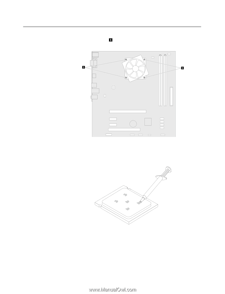
Chapter 9. Replacing hardware 5. Remove the 4 screws that secure the heatsink assembly to the system board. 6. Lift the defective heatsink assembly away from the system board. 7. Use a thermal grease syringe to place five drops of grease on the top of the microprocessor. Each drop of grease should be 0.03ml (3 tick marks on the grease syringe). 8. Fit the new heatsink assembly back onto the heatsink retention bracket. 9. Reconnect the disconnected cables to the system board. 10. Refer to "Completing the installation". 49
-
 1
1 -
2
-
3
-
4
-
5
-
6
-
7
-
8
-
9
-
10
-
11
-
12
-
13
-
14
-
15
-
16
-
17
-
18
-
19
-
20
-
21
-
22
-
23
-
24
-
25
-
26
-
27
-
28
-
29
-
30
-
31
-
32
-
33
-
34
-
35
-
36
-
37
-
38
-
39
-
40
-
41
-
42
-
43
-
44
-
45
-
 46
46 -
 47
47 -
 48
48 -
 49
49 -
 50
50 -
 51
51 -
 52
52 -
 53
53 -
 54
54 -
 55
55 -
 56
56 -
57
-
58
-
59
-
60
-
61
-
62
-
63
-
64
-
65
-
66
 |
 |
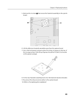
Chapter 9. Replacing hardware
49
5. Remove the 4 screws
that secure the heatsink assembly to the system
board.
6. Lift the defective heatsink assembly away from the system board.
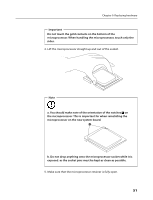
7. Use a thermal grease syringe to place five drops of grease on the top of
the microprocessor. Each drop of grease should be 0.03ml (3 tick marks
on the grease syringe).
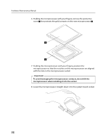
8. Fit the new heatsink assembly back onto the heatsink retention bracket.
9. Reconnect the disconnected cables to the system board.
10. Refer to “Completing the installation”.