Lenovo ThinkCentre Edge 62 Hardware Maintenance Manual - Page 110
Replacing the microprocessor fan
 |
View all Lenovo ThinkCentre Edge 62 manuals
Add to My Manuals
Save this manual to your list of manuals |
Page 110 highlights
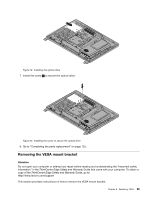
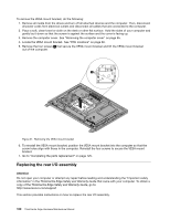
9. Remove the three screws 1 that secure the power supply. Figure 25. Removing the three screws that secure the power supply 10. To reinstall the power supply, reinstall the two screws that secure the power cord connector to the power connector bracket. See "Replacing the rear I/O assembly" on page 100 11. Position the new power supply in the computer and align the three screw holes in the new power supply with those in the computer main bracket. Install the three screws to secure the new power supply. 12. Route the new power cord connector cable, and then reinstall the rear I/O assembly. See "Replacing the rear I/O assembly" on page 100. 13. Connect the new power supply cables to the power supply connectors on the system board. See "System board parts and connectors" on page 88. 14. Reinstall the system board shield. See "Removing and reinstalling the system board shield" on page 102. 15. Reinstall the VESA mount bracket. See "Removing the VESA mount bracket" on page 99. 16. Reinstall the computer cover. See "Removing the computer cover" on page 95. 17. Go to "Completing the parts replacement" on page 125. Replacing the microprocessor fan Attention Do not open your computer or attempt any repair before reading and understanding the "Important safety information" in the ThinkCentre Edge Safety and Warranty Guide that came with your computer. To obtain a copy of the ThinkCentre Edge Safety and Warranty Guide, go to: http://www.lenovo.com/support This section provides instructions on how to replace the microprocessor fan. To replace the microprocessor fan, do the following: 104 ThinkCentre Edge Hardware Maintenance Manual
-
 1
1 -
2
-
3
-
4
-
5
-
6
-
7
-
8
-
9
-
10
-
11
-
12
-
13
-
14
-
15
-
16
-
17
-
18
-
19
-
20
-
21
-
22
-
23
-
24
-
25
-
26
-
27
-
28
-
29
-
30
-
31
-
32
-
33
-
34
-
35
-
36
-
37
-
38
-
39
-
40
-
41
-
42
-
43
-
44
-
45
-
46
-
47
-
48
-
49
-
50
-
51
-
52
-
53
-
54
-
55
-
56
-
57
-
58
-
59
-
60
-
61
-
62
-
63
-
64
-
65
-
66
-
67
-
68
-
69
-
70
-
71
-
72
-
73
-
74
-
75
-
76
-
77
-
78
-
79
-
80
-
81
-
82
-
83
-
84
-
85
-
86
-
87
-
88
-
89
-
90
-
91
-
92
-
93
-
94
-
95
-
96
-
97
-
98
-
99
-
100
-
101
-
102
-
103
-
104
-
 105
105 -
 106
106 -
 107
107 -
 108
108 -
 109
109 -
 110
110 -
 111
111 -
 112
112 -
 113
113 -
 114
114 -
 115
115 -
116
-
117
-
118
-
119
-
120
-
121
-
122
-
123
-
124
-
125
-
126
-
127
-
128
-
129
-
130
-
131
-
132
-
133
-
134
-
135
-
136
-
137
-
138
-
139
-
140
-
141
-
142
-
143
-
144
-
145
-
146
-
147
-
148
-
149
-
150
-
151
-
152
-
153
-
154
-
155
-
156
-
157
-
158
-
159
-
160
-
161
-
162
-
163
-
164
-
165
-
166
-
167
-
168
-
169
-
170
-
171
-
172
-
173
-
174
-
175
-
176
-
177
-
178
-
179
-
180
-
181
-
182
 |
 |
