Lenovo ThinkCentre Edge 62 Hardware Maintenance Manual - Page 125
Grasp the microprocessor on the sides and lift it straight up and out of the socket. Do not touch
 |
View all Lenovo ThinkCentre Edge 62 manuals
Add to My Manuals
Save this manual to your list of manuals |
Page 125 highlights
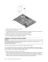
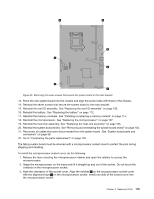
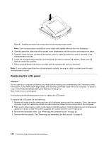
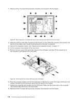
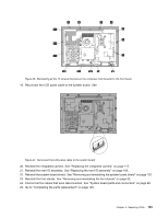
Figure 40. Removing the seven screws that secure the system board to the main bracket 13. Place the new system board into the chassis and align the screw holes with those in the chassis. 14. Reinstall the seven screws that secure the system board to the main bracket. 15. Reinstall the rear I/O assembly. See "Replacing the rear I/O assembly" on page 100. 16. Reinstall the battery. See "Replacing the battery" on page 112. 17. Reinstall the memory modules. See "Installing or replacing a memory module" on page 114. 18. Reinstall the microprocessor. See "Replacing the microprocessor" on page 107. 19. Reinstall the heat sink assembly. See "Replacing the heat sink assembly" on page 105. 20. Reinstall the system board shield. See "Removing and reinstalling the system board shield" on page 102. 21. Reconnect all cables that were disconnected from the system board. See "System board parts and connectors" on page 88. 22. Go to "Completing the parts replacement" on page 125. The failing system board must be returned with a microprocessor socket cover to protect the pins during shipping and handling. To install the microprocessor socket cover, do the following: 1. Release the lever securing the microprocessor retainer and open the retainer to access the microprocessor. 2. Grasp the microprocessor on the sides and lift it straight up and out of the socket. Do not touch the contacts on the microprocessor socket. 3. Note the orientation of the socket cover. Align the notches 1 on the microprocessor socket cover with the alignment keys 2 on the microprocessor socket. Install one side of the socket cover into the microprocessor socket. Chapter 8. Replacing FRUs 119
-
 1
1 -
2
-
3
-
4
-
5
-
6
-
7
-
8
-
9
-
10
-
11
-
12
-
13
-
14
-
15
-
16
-
17
-
18
-
19
-
20
-
21
-
22
-
23
-
24
-
25
-
26
-
27
-
28
-
29
-
30
-
31
-
32
-
33
-
34
-
35
-
36
-
37
-
38
-
39
-
40
-
41
-
42
-
43
-
44
-
45
-
46
-
47
-
48
-
49
-
50
-
51
-
52
-
53
-
54
-
55
-
56
-
57
-
58
-
59
-
60
-
61
-
62
-
63
-
64
-
65
-
66
-
67
-
68
-
69
-
70
-
71
-
72
-
73
-
74
-
75
-
76
-
77
-
78
-
79
-
80
-
81
-
82
-
83
-
84
-
85
-
86
-
87
-
88
-
89
-
90
-
91
-
92
-
93
-
94
-
95
-
96
-
97
-
98
-
99
-
100
-
101
-
102
-
103
-
104
-
105
-
106
-
107
-
108
-
109
-
110
-
111
-
112
-
113
-
114
-
115
-
116
-
117
-
118
-
119
-
 120
120 -
 121
121 -
 122
122 -
 123
123 -
 124
124 -
 125
125 -
 126
126 -
 127
127 -
 128
128 -
 129
129 -
 130
130 -
131
-
132
-
133
-
134
-
135
-
136
-
137
-
138
-
139
-
140
-
141
-
142
-
143
-
144
-
145
-
146
-
147
-
148
-
149
-
150
-
151
-
152
-
153
-
154
-
155
-
156
-
157
-
158
-
159
-
160
-
161
-
162
-
163
-
164
-
165
-
166
-
167
-
168
-
169
-
170
-
171
-
172
-
173
-
174
-
175
-
176
-
177
-
178
-
179
-
180
-
181
-
182
 |
 |
