Lenovo ThinkPad Edge E425 Hardware Maintenance Manual - Page 67
Hard disk drive assembly, 1030 Bottom slot cover
 |
View all Lenovo ThinkPad Edge E425 manuals
Add to My Manuals
Save this manual to your list of manuals |
Page 67 highlights
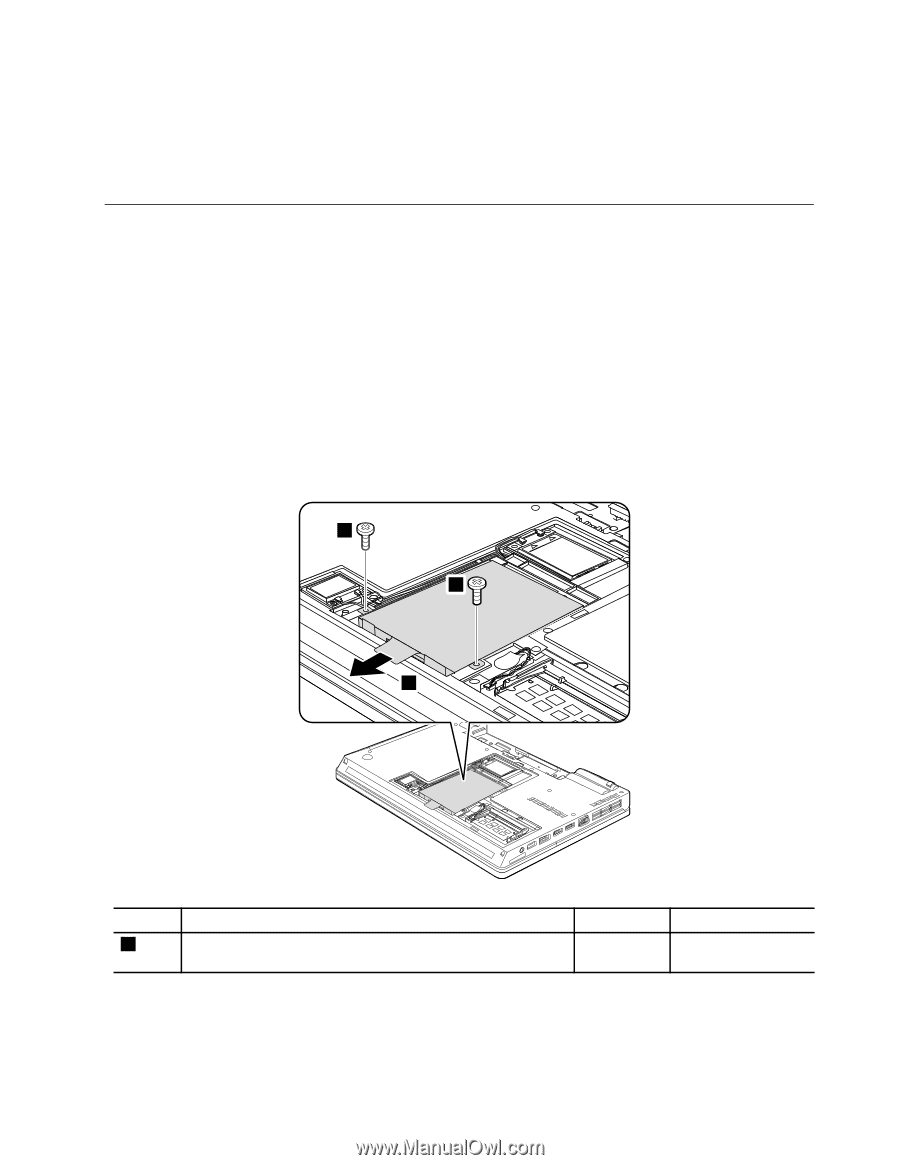
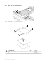
Table 12. Removal steps of memory modules (continued) When installing: Insert the notched end of the memory module into the socket. Press the memory module firmly, and pivot it until it snaps into place. Make sure that it is firmly installed in the slot and does not move easily. 1060 Hard disk drive assembly For access, remove these FRUs in order: • "1010 Battery pack" on page 56 • "1030 Bottom slot cover" on page 58 Attention: • Do not drop the drive or apply any physical shock to it. The drive is sensitive to physical shock. Improper handling can cause damage and permanent loss of data. • Before removing the drive, have the user make a backup copy of all the information on it if possible. • Never remove the drive while the computer is operating or is in suspend mode. Table 13. Removal steps of HDD assembly 1 1 2 Step 1 Screw (quantity) M2 × 6 mm, wafer-head, nylon-coated (2) Color Black Torque 0.181 Nm (1.85 kgfcm) Chapter 8. Removing and replacing a FRU 61
-
 1
1 -
2
-
3
-
4
-
5
-
6
-
7
-
8
-
9
-
10
-
11
-
12
-
13
-
14
-
15
-
16
-
17
-
18
-
19
-
20
-
21
-
22
-
23
-
24
-
25
-
26
-
27
-
28
-
29
-
30
-
31
-
32
-
33
-
34
-
35
-
36
-
37
-
38
-
39
-
40
-
41
-
42
-
43
-
44
-
45
-
46
-
47
-
48
-
49
-
50
-
51
-
52
-
53
-
54
-
55
-
56
-
57
-
58
-
59
-
60
-
61
-
 62
62 -
 63
63 -
 64
64 -
 65
65 -
 66
66 -
 67
67 -
 68
68 -
 69
69 -
 70
70 -
 71
71 -
 72
72 -
73
-
74
-
75
-
76
-
77
-
78
-
79
-
80
-
81
-
82
-
83
-
84
-
85
-
86
-
87
-
88
-
89
-
90
-
91
-
92
-
93
-
94
-
95
-
96
-
97
-
98
-
99
-
100
-
101
-
102
-
103
-
104
-
105
-
106
-
107
-
108
-
109
-
110
-
111
-
112
-
113
-
114
-
115
-
116
-
117
-
118
-
119
-
120
-
121
-
122
-
123
-
124
-
125
-
126
-
127
-
128
-
129
-
130
-
131
-
132
-
133
-
134
 |
 |