Lenovo ThinkPad Edge E425 Hardware Maintenance Manual - Page 97
Wireless LAN antenna assembly, wireless WAN antenna assembly, and LCD rear cover assembly
 |
View all Lenovo ThinkPad Edge E425 manuals
Add to My Manuals
Save this manual to your list of manuals |
Page 97 highlights
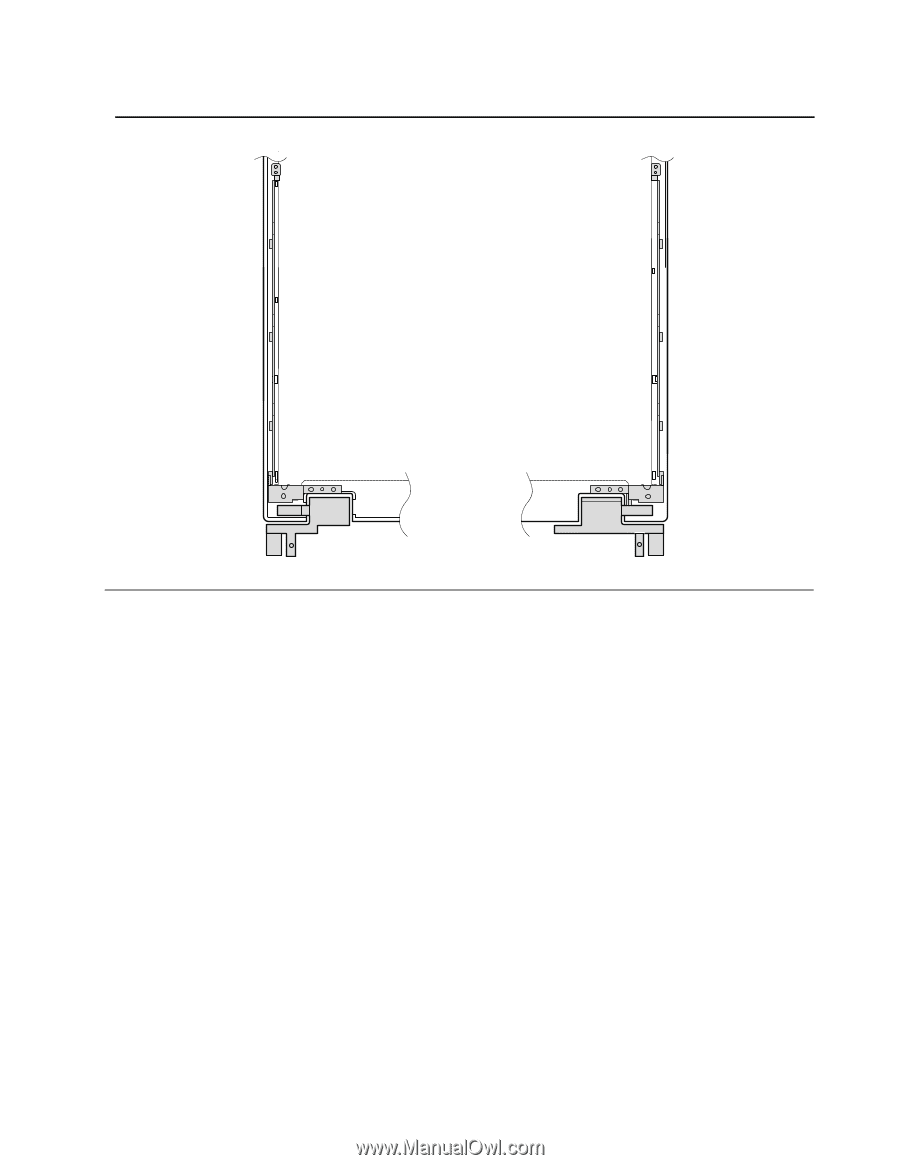
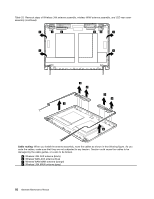
Table 32. Removal steps of hinges (continued) 2040 Wireless LAN antenna assembly, wireless WAN antenna assembly, and LCD rear cover assembly For access, remove these FRUs in order: • "1010 Battery pack" on page 56 • "1030 Bottom slot cover" on page 58 • "1040 Optical drive or travel cover" on page 59 • "1070 PCI Express Mini Card for wireless LAN" on page 63 • "1080 PCI Express Mini Card for wireless WAN" on page 64 • "1080 mSATA solid state drive" on page 65 • "1110 Keyboard" on page 67 • "1120 Top case assembly" on page 68 • "1190 LCD unit" on page 84 • "2010 LCD bezel assembly" on page 86 • "2020 Integrated camera" on page 87 • "2030 LCD panel, LCD cable, LCD rear cover assembly, and hinges" on page 88 Table 33. Removal steps of Wireless LAN antenna assembly, wireless WAN antenna assembly, and LCD rear cover assembly Release the antenna cables from the cable guides of the LCD rear cover assembly and from the hinges. Chapter 8. Removing and replacing a FRU 91
-
 1
1 -
2
-
3
-
4
-
5
-
6
-
7
-
8
-
9
-
10
-
11
-
12
-
13
-
14
-
15
-
16
-
17
-
18
-
19
-
20
-
21
-
22
-
23
-
24
-
25
-
26
-
27
-
28
-
29
-
30
-
31
-
32
-
33
-
34
-
35
-
36
-
37
-
38
-
39
-
40
-
41
-
42
-
43
-
44
-
45
-
46
-
47
-
48
-
49
-
50
-
51
-
52
-
53
-
54
-
55
-
56
-
57
-
58
-
59
-
60
-
61
-
62
-
63
-
64
-
65
-
66
-
67
-
68
-
69
-
70
-
71
-
72
-
73
-
74
-
75
-
76
-
77
-
78
-
79
-
80
-
81
-
82
-
83
-
84
-
85
-
86
-
87
-
88
-
89
-
90
-
91
-
 92
92 -
 93
93 -
 94
94 -
 95
95 -
 96
96 -
 97
97 -
 98
98 -
 99
99 -
 100
100 -
 101
101 -
 102
102 -
103
-
104
-
105
-
106
-
107
-
108
-
109
-
110
-
111
-
112
-
113
-
114
-
115
-
116
-
117
-
118
-
119
-
120
-
121
-
122
-
123
-
124
-
125
-
126
-
127
-
128
-
129
-
130
-
131
-
132
-
133
-
134
 |
 |