Lenovo ThinkPad Edge E425 Hardware Maintenance Manual - Page 86
CPU, 1110 Keyboard
 |
View all Lenovo ThinkPad Edge E425 manuals
Add to My Manuals
Save this manual to your list of manuals |
Page 86 highlights
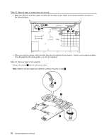
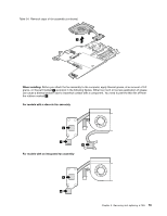
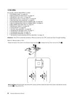
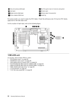
1170 CPU For access, remove these FRUs in order: • "1010 Battery pack" on page 56 • "1020 ExpressCard blank bezel" on page 57 • "1030 Bottom slot cover" on page 58 • "1040 Optical drive or travel cover" on page 59 • "1060 Hard disk drive assembly" on page 61 • "1070 PCI Express Mini Card for wireless LAN" on page 63 • "1080 PCI Express Mini Card for wireless WAN" on page 64 • "1080 mSATA solid state drive" on page 65 • "1090 Backup battery" on page 66 • "1110 Keyboard" on page 67 • "1120 Top case assembly" on page 68 • "1130 Bluetooth daughter card" on page 71 • "1140 Express sub card" on page 72 • "1150 Speaker assembly" on page 73 • "1160 System board assembly and fan assembly" on page 74 Attention: The CPU is extremely sensitive. When you service the CPU, avoid any kind of rough handling. Table 25. Removal steps of CPU Rotate the head of the screw in the direction shown by arrow 1 to release the lock, then remove the CPU 2 . 2 1 3 When installing: Place the CPU above the CPU socket, and then rotate the head of the screw in the direction shown by arrow 3 to secure the CPU. 80 Hardware Maintenance Manual
-
 1
1 -
2
-
3
-
4
-
5
-
6
-
7
-
8
-
9
-
10
-
11
-
12
-
13
-
14
-
15
-
16
-
17
-
18
-
19
-
20
-
21
-
22
-
23
-
24
-
25
-
26
-
27
-
28
-
29
-
30
-
31
-
32
-
33
-
34
-
35
-
36
-
37
-
38
-
39
-
40
-
41
-
42
-
43
-
44
-
45
-
46
-
47
-
48
-
49
-
50
-
51
-
52
-
53
-
54
-
55
-
56
-
57
-
58
-
59
-
60
-
61
-
62
-
63
-
64
-
65
-
66
-
67
-
68
-
69
-
70
-
71
-
72
-
73
-
74
-
75
-
76
-
77
-
78
-
79
-
80
-
 81
81 -
 82
82 -
 83
83 -
 84
84 -
 85
85 -
 86
86 -
 87
87 -
 88
88 -
 89
89 -
 90
90 -
 91
91 -
92
-
93
-
94
-
95
-
96
-
97
-
98
-
99
-
100
-
101
-
102
-
103
-
104
-
105
-
106
-
107
-
108
-
109
-
110
-
111
-
112
-
113
-
114
-
115
-
116
-
117
-
118
-
119
-
120
-
121
-
122
-
123
-
124
-
125
-
126
-
127
-
128
-
129
-
130
-
131
-
132
-
133
-
134
 |
 |