Lenovo ThinkPad X200 Hardware Maintenance Manual - Page 116
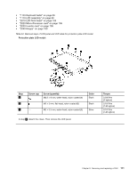
LCD panel, LCD bracket L and R, and LCD cable
 |
View all Lenovo ThinkPad X200 manuals
Add to My Manuals
Save this manual to your list of manuals |
Page 116 highlights
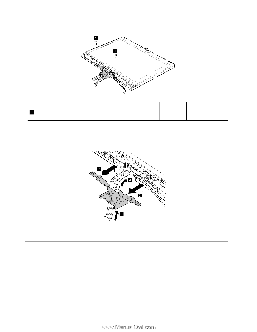
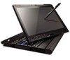
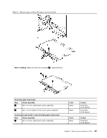
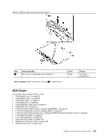
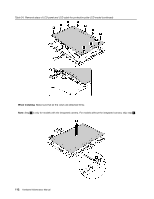
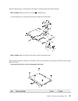
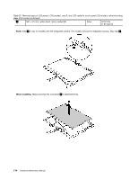
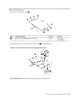
Table 33. Removal steps of hinge Step 1 Screw (quantity) M2.5 × 6 mm, wafer-head, nylon-coated (2) Color Black Torque 0.392 Nm (4 kgfcm) Detach the hinge from the LCD rear cover, and gently pull the cables out through the guide hole in the hinge. Pull them all at once. As you pull them, be sure not to subject them to any tension, which could cause them to be damaged by the cable guides, or could break a wire. 2050 LCD panel, LCD bracket L and R, and LCD cable For access, remove these FRUs in order: • "1010 Digitizer pen" on page 61 • "1020 Battery pack" on page 61 • "1050 Hinge caps" on page 67 • "1060 Keyboard" on page 68 • "1070 Extension cable card" on page 71 • "1080 Palm rest" on page 72 • "1100 PCI Express Mini Card for wireless LAN/WiMAX" on page 76 • "1110 PCI Express Mini Card for wireless WAN" on page 78 • "1120 Intel Turbo Memory Minicard or Wireless USB PCI Express Half-Mini Card" on page 80 110 Hardware Maintenance Manual
-
 1
1 -
2
-
3
-
4
-
5
-
6
-
7
-
8
-
9
-
10
-
11
-
12
-
13
-
14
-
15
-
16
-
17
-
18
-
19
-
20
-
21
-
22
-
23
-
24
-
25
-
26
-
27
-
28
-
29
-
30
-
31
-
32
-
33
-
34
-
35
-
36
-
37
-
38
-
39
-
40
-
41
-
42
-
43
-
44
-
45
-
46
-
47
-
48
-
49
-
50
-
51
-
52
-
53
-
54
-
55
-
56
-
57
-
58
-
59
-
60
-
61
-
62
-
63
-
64
-
65
-
66
-
67
-
68
-
69
-
70
-
71
-
72
-
73
-
74
-
75
-
76
-
77
-
78
-
79
-
80
-
81
-
82
-
83
-
84
-
85
-
86
-
87
-
88
-
89
-
90
-
91
-
92
-
93
-
94
-
95
-
96
-
97
-
98
-
99
-
100
-
101
-
102
-
103
-
104
-
105
-
106
-
107
-
108
-
109
-
110
-
 111
111 -
 112
112 -
 113
113 -
 114
114 -
 115
115 -
 116
116 -
 117
117 -
 118
118 -
 119
119 -
 120
120 -
 121
121 -
122
-
123
-
124
-
125
-
126
-
127
-
128
-
129
-
130
-
131
-
132
-
133
-
134
-
135
-
136
-
137
-
138
-
139
-
140
-
141
-
142
-
143
-
144
-
145
-
146
-
147
-
148
-
149
-
150
-
151
-
152
-
153
-
154
-
155
-
156
-
157
-
158
-
159
-
160
-
161
-
162
-
163
-
164
-
165
-
166
-
167
-
168
-
169
-
170
-
171
-
172
-
173
-
174
-
175
-
176
-
177
-
178
-
179
-
180
-
181
-
182
-
183
-
184
-
185
-
186
-
187
-
188
-
189
-
190
-
191
-
192
-
193
-
194
-
195
-
196
-
197
-
198
 |
 |