LiftMaster 3850 3850 Elite Series Manual - Page 15
Attach the Emergency Release Ropeand Handle, Electrical Requirements, INSTALLATION STEP 10 - battery removal
 |
View all LiftMaster 3850 manuals
Add to My Manuals
Save this manual to your list of manuals |
Page 15 highlights
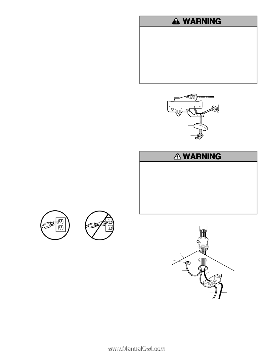
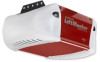
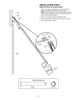
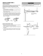
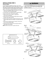
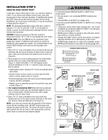
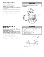
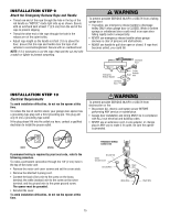
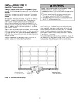
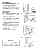
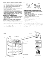
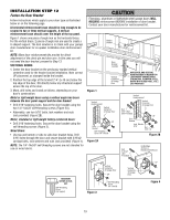
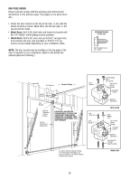
INSTALLATION STEP 9 Attach the Emergency Release Rope and Handle • Thread one end of the rope through the hole in the top of the red handle so "NOTICE" reads right side up as shown. Secure with an overhand knot at least 1" (2.5 cm) from the end of the rope to prevent slipping. • Thread the other end of the rope through the hole in the release arm of the outer trolley. • Adjust rope length so the handle is 6 feet (1.8 m) above the floor. Ensure that the rope and handle clear the tops of all vehicles to avoid entanglement. Secure with an overhand knot. NOTE: If it is necessary to cut the rope, heat seal the cut end with a match or lighter to prevent unraveling. To prevent possible SERIOUS INJURY or DEATH from a falling garage door: • If possible, use emergency release handle to disengage trolley ONLY when garage door is CLOSED. Weak or broken springs or unbalanced door could result in an open door falling rapidly and/or unexpectedly. • NEVER use emergency release handle unless garage doorway is clear of persons and obstructions. • NEVER use handle to pull door open or closed. If rope knot becomes untied, you could fall. Overhand Knot Emergency Release Handle Rope NOTICE Trolley Release Arm Overhand Knot INSTALLATION STEP 10 Electrical Requirements To avoid installation difficulties, do not run the opener at this time. To reduce the risk of electric shock, your garage door opener has a grounding type plug with a third grounding pin. This plug will only fit into a grounding type outlet. If the plug doesn't fit into the outlet you have, contact a qualified electrician to install the proper outlet. To prevent possible SERIOUS INJURY or DEATH from electrocution or fire: • Disconnect ALL electric and battery power BEFORE performing ANY service or maintenance. • Garage door installation and wiring MUST be in compliance with ALL local electrical and building codes. • NEVER use an extension cord, 2-wire adapter, or change plug in ANY way to make it fit outlet. Be sure the opener is grounded. RIGHT WRONG If permanent wiring is required by your local code, refer to the following procedure. To make a permanent connection through the 7/8" (2 cm) hole in the top of the motor unit: • Remove the motor unit cover screws and set the cover aside. • Remove the attached 3-prong cord. • Connect the black (line) wire to the screw on the brass terminal; the white (neutral) wire to the screw on the silver terminal; and the ground wire to the green ground screw. The opener must be grounded. • Reinstall the cover. To avoid installation difficulties, do not run the opener at this time. PERMANENT WIRING CONNECTION Ground Tab Green Ground Screw Ground Wire Black Wire White Wire Black Wire 15
-
 1
1 -
2
-
3
-
4
-
5
-
6
-
7
-
8
-
9
-
 10
10 -
 11
11 -
 12
12 -
 13
13 -
 14
14 -
 15
15 -
 16
16 -
 17
17 -
 18
18 -
 19
19 -
 20
20 -
21
-
22
-
23
-
24
-
25
-
26
-
27
-
28
-
29
-
30
-
31
-
32
-
33
-
34
-
35
-
36
-
37
-
38
-
39
-
40
 |
 |