LiftMaster 3850 3850 Elite Series Manual - Page 18
Mounting And Wiring The Safety Reversing Sensors - troubleshooting
 |
View all LiftMaster 3850 manuals
Add to My Manuals
Save this manual to your list of manuals |
Page 18 highlights
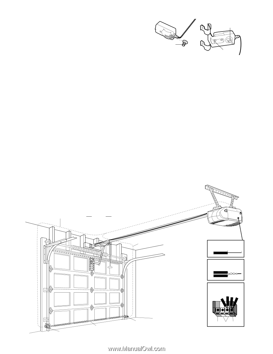
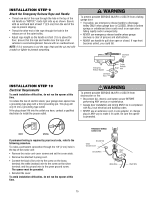
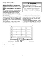
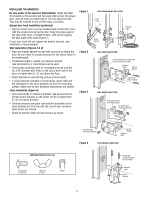
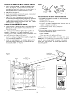
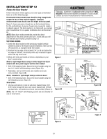
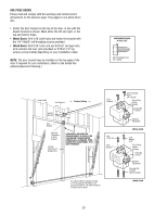
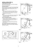
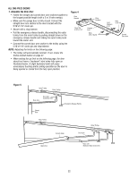
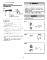
MOUNTING AND WIRING THE SAFETY REVERSING SENSORS • Slide a 1/4"-20x1/2" carriage bolt head into the slot on each sensor. Use wing nuts to fasten sensors to brackets, with lenses pointing toward each other across the door. Be sure the lens is not obstructed by a bracket extension (Figure 5). • Finger tighten the wing nuts. • Run the wires from both sensors to the opener. Use insulated staples to secure wire to wall and ceiling. • Strip 7/16" (11 mm) of insulation from each set of wires. Separate white and white/black wires sufficiently to connect to the opener quick-connect terminals. Twist like colored wires together. Insert wires into quick-connect holes: white to white and white/black to grey (Figure 6). ALIGNING THE SAFETY REVERSING SENSORS • Plug in the opener. The indicator lights in both the sending and receiving eyes will glow steadily if wiring connections and alignment are correct. The sending eye amber indicator light will glow regardless of alignment or obstruction. If the green indicator light in the receiving eye is off, dim, or flickering (and the invisible light beam path is not obstructed), alignment is required. • Loosen the sending eye wing nut and readjust, aiming directly at the receiving eye. Lock in place. • Loosen the receiving eye wing nut and adjust sensor until it receives the sender's beam. When the green indicator light glows steadily, tighten the wing nut. Figure 5 Wing Nut 1/4"-20 Carriage Bolt 1/4"-20x1/2" Lens TROUBLESHOOTING THE SAFETY REVERSING SENSORS 1. If the sending eye indicator light does not glow steadily after installation, check for: • Electric power to the opener. • A short in the white or white/black wires. These can occur at staples, or at opener connections. • Incorrect wiring between sensors and opener. • A broken wire. 2. If the sending eye indicator light glows steadily but the receiving eye indicator light doesn't: • Check alignment. • Check for an open wire to the receiving eye. 3. If the receiving eye indicator light is dim, realign either sensor. NOTE: When the invisible beam path is obstructed or misaligned while the door is closing, the door will reverse. If the door is already open, it will not close. The opener lights will blink 10 times. See page 16. Figure 6 Bell Wire Finished Ceiling Connect Wire to Quick-Connect Terminals Bell Wire 1. Strip wire 7/16" (11 mm) 7/16" (11 mm) 2. Twist like colored wires together 3. To insert or release wire, push in tab with screwdriver tip Safety Reversing Sensor Invisible Light Beam Protection Area Safety Reversing Sensor 18 Red White Grey Quick-Connect Terminals
-
 1
1 -
2
-
3
-
4
-
5
-
6
-
7
-
8
-
9
-
10
-
11
-
12
-
 13
13 -
 14
14 -
 15
15 -
 16
16 -
 17
17 -
 18
18 -
 19
19 -
 20
20 -
 21
21 -
 22
22 -
 23
23 -
24
-
25
-
26
-
27
-
28
-
29
-
30
-
31
-
32
-
33
-
34
-
35
-
36
-
37
-
38
-
39
-
40
 |
 |