Netgear FS726T FS726T User Manual - Page 43
Normal Assignment On, Ports 1 To 8, Port 8, D-4
 |
UPC - 606449038415
View all Netgear FS726T manuals
Add to My Manuals
Save this manual to your list of manuals |
Page 43 highlights
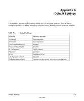
Smart Switch Series Software Manual Figure D-4 shows the RJ-45 plug and RJ-45 connector. Figure D-4: RJ-45 Plug and RJ-45 Connector with Built-in LEDs Table D-2 lists the pin assignments for the 10/100 Mbps RJ-45 plug and the RJ-45 connector. Table-D-2. 10/100 Mbps RJ-45 Plug and RJ-45 Connector Pin Assignments PIN 1 2 NORMAL ASSIGNMENT ON PORTS 1 TO 8 Input Receive Data + Input Receive Data - 3 Output Transmit Data + 6 Output Transmit Data - 4, 5, 7, 8 Internal termination, not used for data transmission UPLINK ASSIGNMENT ON PORT 8 Output Transmit Data + Output Transmit Data - Input Receive Data + Input Receive Data - Table E-2 lists the pin assignments for the 100/1000 Mbps RJ-45 plug and the RJ-45 connector. Cabling Guidelines D-7 July 2005
-
 1
1 -
2
-
3
-
4
-
5
-
6
-
7
-
8
-
9
-
10
-
11
-
12
-
13
-
14
-
15
-
16
-
17
-
18
-
19
-
20
-
21
-
22
-
23
-
24
-
25
-
26
-
27
-
28
-
29
-
30
-
31
-
32
-
33
-
34
-
35
-
36
-
37
-
 38
38 -
 39
39 -
 40
40 -
 41
41 -
 42
42 -
 43
43 -
 44
44 -
 45
45 -
 46
46 -
 47
47 -
 48
48 -
49
-
50
 |
 |
