NordicTrack Cxt1400 Uk Manual - Page 6
Hold a Hub Cover 75 and a Crank Arm 36 against
 |
View all NordicTrack Cxt1400 manuals
Add to My Manuals
Save this manual to your list of manuals |
Page 6 highlights
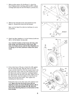
1. While another person lifts the Base (1), attach the Front Stabiliser (6) to the Base with two M10 x 80mm Carriage Bolts (82) and two M10 Nylon Locknuts (81). 1 82 2. Remove the indicated screw and bracket from the 2 Base (1). Discard the screw and the bracket. Next, turn the Base Foot (26) into the Base (1) as far as possible. 3. Attach the Rear Stabiliser (7) to the Frame (2) with two M10 x 127mm Button Screws (83). 3 Next, hold the handle on the Frame (2) firmly with both hands, pull and hold the Latch Lever (68), lower the Frame slowly until the Rear Stabiliser (7) is resting on the floor, and then release the Latch Lever. 81 6 81 1 1 26 Screw 83 7 Bracket Handle 68 2 4. Hold a Hub Cover (75) and a Crank Arm (36) against the left Crank Hub (38). Align the holes in the Hub Cover and the Crank Arm with the unused holes in the left Crank Hub. Next, insert four Hub Screws (87) into the Hub Cover and the Crank Arm, and finger tighten the Hub Screws into the left Crank Hub. Tighten one of the Hub Screws, and then tighten the Hub Screw farthest from the first Hub Screw. Then, tighten the remaining two Hub Screws. Repeat this step on the other side of the elliptical exerciser. Make sure that the Crank Arms (36) are attached so that one Crank Bushing Sleeve (43) is at the top of the Side Shields (28, 29) when the other Crank Bushing Sleeve is at the bottom of the Side Shields. 6 4 38 36 75 87 87 43 43 36 29 28
-
 1
1 -
 2
2 -
 3
3 -
 4
4 -
 5
5 -
 6
6 -
 7
7 -
 8
8 -
 9
9 -
 10
10 -
 11
11 -
 12
12 -
13
-
14
-
15
-
16
-
17
-
18
-
19
-
20
-
21
-
22
-
23
-
24
-
25
-
26
-
27
-
28
-
29
-
30
-
31
-
32
 |
 |
