NordicTrack Cxt1400 Uk Manual - Page 7
the Pulse Wire 121. Insert the Wire Harnesses into
 |
View all NordicTrack Cxt1400 manuals
Add to My Manuals
Save this manual to your list of manuals |
Page 7 highlights
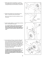
5. While another person holds the Upright (3), connect the Upper Wire Harness (48) to the Lower Wire Harness (49). Gently pull the upper end of the Upper Wire Harness to remove any slack, and insert the Upright into the Base (1). Attach the Upright with an M8 x 69mm Button Bolt (80), an M8 Split Washer (90), and an M8 Jamnut (79). Do not tighten the Button Bolt yet; make sure that the Jamnut is in the hexagonal hole in the Base. Next, finger tighten two M8 x 23mm Button Screws (84) with M8 Split Washers (90) into the Base (1). Do not tighten the Button Screws yet. Attach the Water Bottle Holder (22) to the Base (1) with two M4 x 14mm Screws (104). 5 80 90 90 84 3 48 49 79 90 84 104 1 22 6. Orient the Transport Handle (119) as shown, and attach it to the Upright (3) with two M8 x 112mm Button Bolts (123) and two M8 Jamnuts (79). While another person holds the Pulse Bar (4) near the Upright (3), connect the two connectors on the Upper Wire Harness (48) to the corresponding connectors on the Pulse Wire (121). Insert the Wire Harnesses into the Upright, and attach the Pulse Bar to the Upright with three M8 x 23mm Button Screws (84) and three M8 Split Washers (90). Orient one of the Upright Covers (17) as shown, and hold it against the Upright (3). Attach the Upright Cover with two M4 x 16mm Round Head Screws (101). Attach the other Upright Cover in the same way. 6 119 123 3 90 84 17 101 79 84 90 121 48 90 4 101 17 7. The Console (5) requires four "D" batteries; alkaline batteries are recommended. Remove the battery cover from the bottom of the Console. Next, insert four batteries into the battery compartment; make sure that the batteries are oriented as shown by the diagram inside the battery compartment. Reattach the battery cover. 7 5 Batteries 8. While another person holds the Console (5) near the Upright (3), connect the two wire harnesses on the Console to the corresponding connectors on the Upper Wire Harness (48). Insert the excess wire harness into the Upright (3). Next, attach the Console to the Upright with four M4 x 16mm Round Head Screws (101). Be careful to avoid pinching the wire harnesses. Batteries 8 Wire Harnesses 48 101 3 Battery Cover 5 7
-
 1
1 -
 2
2 -
 3
3 -
 4
4 -
 5
5 -
 6
6 -
 7
7 -
 8
8 -
 9
9 -
 10
10 -
 11
11 -
 12
12 -
13
-
14
-
15
-
16
-
17
-
18
-
19
-
20
-
21
-
22
-
23
-
24
-
25
-
26
-
27
-
28
-
29
-
30
-
31
-
32
 |
 |
