NordicTrack Walkfit 5500 Treadmill English Manual - Page 6
Connect, Tension, Spring, Sensor
 |
View all NordicTrack Walkfit 5500 Treadmill manuals
Add to My Manuals
Save this manual to your list of manuals |
Page 6 highlights
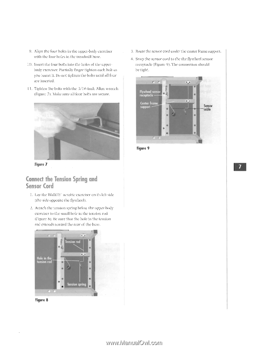
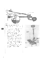
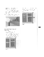
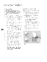
9. Align the Four holes in the upper-body exerciser with the four holes in the treadmill base. 10. Insert Ole four bolls hill) the holes of the upperbody exerciser. l'ari hilly linger lighten each boll as you insert it. Do not lighten ihe hells until all four are inserted. I I. Tighten the bolts with the I/ 1 6-inch Allen wrench (Figure 7). Make sure all flour bolts are secure. .3. Route the sensor cord under the center frame support. 4. Snap the sensor cord to the the flywheel Se.IISO rc•ecpIacIc (Figure 9). The cinmection should he tight. Flywheel sensor receptacle • Center frame support Sensor cable Figure 7 Connect the Tension Spring and Sensor Cord 1. Lay the [Valhi:it aerobic exerciser on its left side (the suit opposite the flywheel). 2. Al ach 1 he tension spring below [he upper-body exerciser to 1 he small hole in the tension rod (Figurc. St. Be sure that [he hole to [he tension rod extends Inward [he rear of 1 he base. r Tension rod Hole in the tension rod • 'r• Figure 9 Figure 8 Tension spring
-
 1
1 -
 2
2 -
 3
3 -
 4
4 -
 5
5 -
 6
6 -
 7
7 -
 8
8 -
 9
9 -
 10
10 -
 11
11 -
 12
12 -
13
-
14
-
15
-
16
-
17
-
18
-
19
-
20
-
21
-
22
-
23
-
24
-
25
-
26
 |
 |