Onkyo TX-8511 Owner Manual - Page 24
Connection, Multi, Remote, Control
 |
View all Onkyo TX-8511 manuals
Add to My Manuals
Save this manual to your list of manuals |
Page 24 highlights
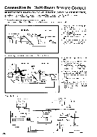
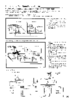
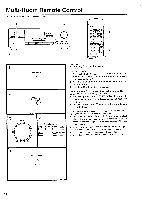
Connection for Multi-Room Remote Control The following instructions apply only to U.S. or Canada model (Xantechm' Multiple-Room systems) Do not plug in the power cord until all connections have been made. When making connections ° through ®, be sure to connect the units as shown in the connection diagram below. Do not make a mistake when connecting the units. A. Connecting components equipped with Onkyo R I jacks Components mounted in a rack should be connected as shown below to enable remote control operation. MAIN ROOM ) SUB ROOM 1. Onkyo components (a) I Speaker A (Main room) \ 7-\ \ TX-8511 7 , Speaker A (Main room) 3. Connecting block - \.- \ Power supply Remote -control 4. Remote Sensor\ 2. Speaker B (Sub room) 7Thr 2. Speaker B (Sub room) 1. Set up the components (a) displaying Onkyo's RI jack. Connect the sub room speaker cables to the speaker B terminal on the '1'X-8511. (C)) 3. Install Connecting Block in the main room, then connect it to the TX-8511. (0) 4. Install Remote Sensor in the subroom, then connect it to the Connect- (0-.)) ing Block in the main room. B. Connecting components not equipped with OnkyoRl jacks 3. (Ecm) itter n MAIN ROOM 5. Emitter\ (e) SUB ROOM Connec block 4. Components(d) TX-8511 I 1. Components(b) / \ \ s.-- .r . A (Main room) Speaker A (Main room) Power supply' Remote control Remote Sensor Speaker B (Sub oom) Speaker B (Sub room) 1. Connect the components (b) to the TX-8511. 2. Make the connections described above in steps 2 through 4 of section A. 3. Install Emitter (c) so that its sensor is directed toward these components, then connect it to the TX-8511. (tD) ■ Operating components which are positioned out of the range of the emitter installed as described above 4. Connect the components (d) to the TX -8511. 5. Install another Emitter (e) so that its sensor is directed toward these components, then connect it to the Connecting Block. (C)) Connection diagram Speaker A (Main Room) 0 0 0 0 L • SPEAKERS A 0000 000000000 000000000 MRx IN Gray Terminal in SPEAKERS B TX-8511 24 Connecting block Emitter U 0 Power supply Lev Speaker B (Sub Room) O Remote Sensor SUB ROOM
-
 1
1 -
2
-
3
-
4
-
5
-
6
-
7
-
8
-
9
-
10
-
11
-
12
-
13
-
14
-
15
-
16
-
17
-
18
-
 19
19 -
 20
20 -
 21
21 -
 22
22 -
 23
23 -
 24
24 -
 25
25 -
 26
26 -
 27
27 -
 28
28
 |
 |
