Onkyo TX-8511 Owner Manual - Page 9
ppeakrym, ecirFe, Connecting:the, speaker, cables, Connecting, speakers
 |
View all Onkyo TX-8511 manuals
Add to My Manuals
Save this manual to your list of manuals |
Page 9 highlights
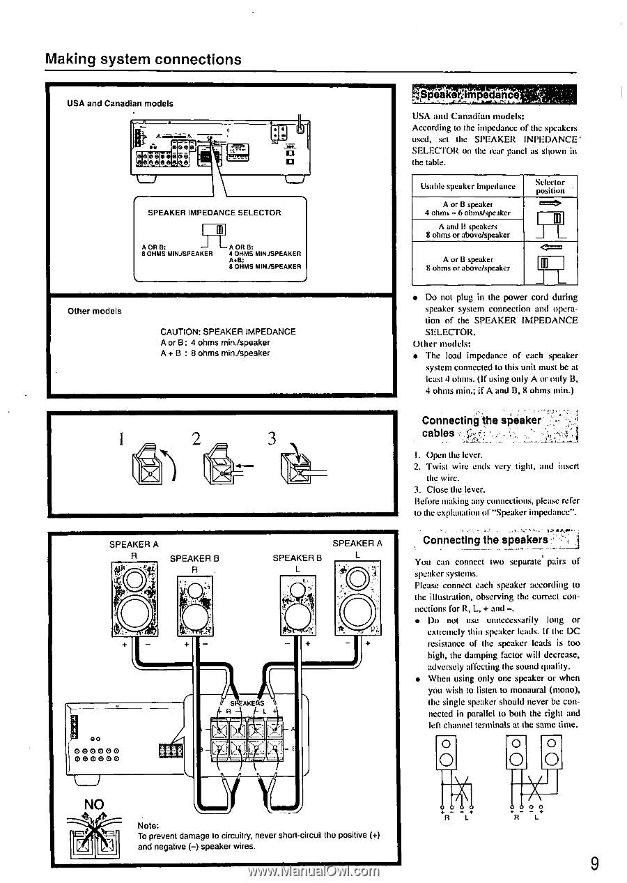
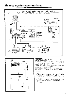
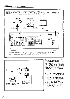
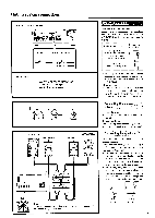
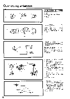
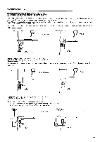
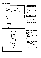
Making system connections USA and Canadian models to. 079 Gee 0000 0 0 0 SI 0 00 e0 0 elej • 4 • 04 -YES- LJ SPEAKER IMPEDANCE SELECTOR [o A OR B: L A OR B: 8 OHMS MINJSPEAKER 4 OHMS MINJSPEAKER A+B: 8 OHMS MINJSPEAKER Other models CAUTION: SPEAKER IMPEDANCE A or B: 4 ohms min./speaker A+ B : 8 ohms min./speaker O SPEAKER A 0.4 SPEAKER B R O SPEAKER A SPEAKER B O 00 000000 000000 NO SPt AKE S R L '/L Note: To prevent damage to circuitry, never short-circuit the positive (+) and negative (-) speaker wires. t..ppeakrym • ecirFe USA and Canadian models: According to the impedance of the speakers used, set the SPEAKER INPEDANCE • SELECTOR on the rear panel as shown iii the table. Usable speaker impedance A or B speaker 4 ohms - 6 ohms/speaker A and B speakers 8 ohms or above/speaker Selector position III _I L A or 13 speaker 8 ohms or above/speaker M _J L • Do not plug in the power cord during speaker system connection and operation of the SPEAKER IMPEDANCE SELECTOR. Other models: • The load impedance of each speaker system connected to this unit must be at least 4 ohms. (If using only A or only B, 4 ohms min.; if A and B, 8 ohms min.) Connecting:the speaker' cables -Atr • - I. Open the lever. 2. Twist wire ends very tight, and insert the wire. 3. Close the lever. Before making any connections, please refer to the explanation of "Speaker impedance". Connecting the speakers ," • You can connect two separate' pairs of speaker systems. Please connect each speaker according to the illustration, observing the correct con- nections for R, L, + and -. • Do not use unnecessarily long or extremely thin speaker leads. If the DC resistance of the speaker leads is too high, the damping factor will decrease, adversely affecting the sound quality. • When using only one speaker or when you wish to listen to monaural (mono), the single speaker should never be con- nected in parallel to both the right and left channel terminals at the same time. 0 0 0 O OO +- - R L 0 0 0 R L 9
-
 1
1 -
2
-
3
-
 4
4 -
 5
5 -
 6
6 -
 7
7 -
 8
8 -
 9
9 -
 10
10 -
 11
11 -
 12
12 -
 13
13 -
 14
14 -
15
-
16
-
17
-
18
-
19
-
20
-
21
-
22
-
23
-
24
-
25
-
26
-
27
-
28
 |
 |