Onkyo TX-8511 Owner Manual - Page 8
morm.
 |
View all Onkyo TX-8511 manuals
Add to My Manuals
Save this manual to your list of manuals |
Page 8 highlights
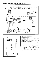
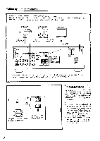
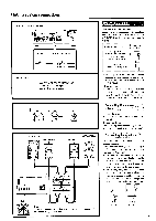
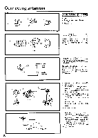
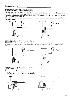
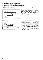
Making system connections Refer to the instruction manual of each component when making connections. On each pair of connectors, the connector (red and marked R) corresponds to the right channel and the connector (white and marked L) to the left channel, and the connector (yellow and marked V) to the Video jack. VDP (VIDEO-1) = 000 VCR (VIDEO-2) OE= TV/Monitor VIDEO OUT AUDIO OUT I I VIDEO IN VIDEO OUT AUDIO IN AUDIO OUT VIDEO IN 0400.4 Wlf iG i ts Irt.004•00.0.010CI !al 1C7001 000 ®O ain11•1 O O O ospo oo cthb o .0000000wo. • Orly Illoiwelal.AUff• 01.101 blir•APLAlell 1.2.0.1.0RS • IN - - l • Dm_orLmie. ■ ONICY0•n•a WOW Vi0t0 mi 0t044. MOM ,. M10 TX4SII [: 101000E CONTROL a oer MP. AC OuREIS .006.110na 11014:ZOILea If there should be interference between the 'I'V and this unit, place this unit as far from the TV as possible. We do not recommend the use of a common TV/FM antenna. (Refer to Connecting anten»ax on page 10, 110 4-- Sf ffE European and worldwide models Capacity is total 100 watts USA and Canadian models Capacity is total 120 watts AC outlet connections The power to components connected to the SWITCHED outlets is turned on and off using the POWER switch (or the SYSTEM switch on models other than USA and Canadian models) on the front panel and remote control. NOTE: • The shape, number and total capacity of the AC outlets may differ according to the model and the area where the unit is purchased. Be careful that other components connected to this unit do not exceed the capacity that is printed on the rear panel above the AC outlets. • (For the European and worldwide models) The remote control cannot be used when the SYSTEM switch on the front panel is set to OFF. 8
-
 1
1 -
2
-
 3
3 -
 4
4 -
 5
5 -
 6
6 -
 7
7 -
 8
8 -
 9
9 -
 10
10 -
 11
11 -
 12
12 -
 13
13 -
14
-
15
-
16
-
17
-
18
-
19
-
20
-
21
-
22
-
23
-
24
-
25
-
26
-
27
-
28
 |
 |
