Onkyo TX-8511 Owner Manual - Page 7
Making, system, connections
 |
View all Onkyo TX-8511 manuals
Add to My Manuals
Save this manual to your list of manuals |
Page 7 highlights
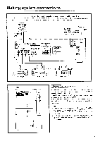
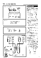
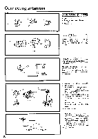
Making system connections ME') Turntable O PHONO 0 OUT Li Refer to the instruction manual of each component when making connections. On each pair of connectors, the connector (red and marked R) corresponds to the right channel and the connector (white and marked L) to the left channel. To wall outlet CAUTION: Do not plug in the power cord until all connections have been made. .NIENN. [63: ra UO Alle. ROM, aunt, ORR,. sow O OOO IPLA I O O OO 0 O1 () () () O 0 O C) C). ROI ..tit ORPROARGE RELlCION SOURER! • R- • orexvo. .40 RAO Calai3O. SOO TR-0511 0 1;1 F.1 1.1 1.1 • 4.'101.{,i..14.14•8•,•4••4••464..100 • 0 O O 141 NER0It CORM°. 04 COS (FRI IIII1{1.1 Kais• rm. lOray abs4 v-111 En J OUTPUT rzt crtz 0 CD player LINE IN • CI=0 LINE OUT FLTEI i .7 O OO Tape deck 11 I y LINE IN LINE OUT • =ID M-E455;7: 0OO Tape deck . -- . . I 1.O. lt ire • • 0 • 6 el • L. , L__,I. ...,.... i•i U • It.. A . r) FC T AM' RI I PI 0 IsbR.uveolirgnrtoet"e.1c!oI ntrol connections Cassette tape decks and a compact disc player that are equipped with an Onkyo RI connector can be operated using the remote control included with this unit. To enable remote control operation of other components, connect the remote control cable as shown at the left. Connect the remote control cable to the black connector with the R I mark, never connect it to the green or gray connector with the fTTg'.: mark. NOTE: • To enable proper remote control operation, both the RI cables and the audio cables must be connected to the units. • This unit's remote control cannot be used to control Onkyo turntables. • An R I remote control cable equipped with 1/8" (3.5 mm) mini jacks is included with any other component installed with an R I connector.
-
 1
1 -
 2
2 -
 3
3 -
 4
4 -
 5
5 -
 6
6 -
 7
7 -
 8
8 -
 9
9 -
 10
10 -
 11
11 -
 12
12 -
13
-
14
-
15
-
16
-
17
-
18
-
19
-
20
-
21
-
22
-
23
-
24
-
25
-
26
-
27
-
28
 |
 |
