Panasonic AW-HS50 Basic Operating Instructions - Page 8
On-screen display OSD, Switching of materials] - switcher
 |
View all Panasonic AW-HS50 manuals
Add to My Manuals
Save this manual to your list of manuals |
Page 8 highlights
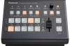
Characteristics Straightforward and flexible operability The control panel layout includes a row of five crosspoint buttons for the A bus and another row of five crosspoint buttons for the B bus. Using these buttons together with the SHIFT button enables a total of ten images to be switched. Cut switches are also made possible by the CUT button. Separate buttons enable the PinP, KEY and FTB functions to be turned ON or OFF in a single-step action. The slide lever is not only used to initiate background transition operations but it can also be allocated to execute PinP and KEY fade in/out operations. Two USER buttons located on control panel. Using these buttons together with the SHIFT button allows a total of four user settings (USER1 to USER4) to be allocated. PinP settings or WIPE pattern settings can be allocated to the USER buttons. On-screen display (OSD) The setting menus can be displayed on an external monitor from the SDI OUT 2 and DVI OUT output connectors. (These menus cannot be displayed using the SDI OUT 1 output connector.) Function for linkup with a remote camera controller using IP connection The unit can be connected to a Panasonic remote camera controller using a network. By linking it with a remote camera controller, it is possible to put together a highly efficient operating environment. Supported remote camera controller: AW-RP50 Only one switcher (the unit) can be linked with a remote camera controller. [Display of camera information] The camera setting information (iris, gain and so on) obtained by the AW-RP50 can be displayed in the AUX output or on the split screens of multi view display. [Transmission of tally information] The unit's ON AIR tally information can be sent to the AW-RP50. [Switching of materials] The bus materials of the switcher (the unit) can be selected from the AW-RP50. They can be switched in tandem with the selection of the camera using the AW-RP50. (Control buses supported: AUX, PVW, PinP, KEY-F) [Focus assist function] By operating the buttons on the AW-RP50, it is possible to switch to the multi view display screen from the full screen display of the camera images. (Control bus supported: AUX) [Parameter operation using PAN/TILT lever and ZOOM button] The PAN/TILT lever and ZOOM button on the AW-RP50 can be used to change the parameters of the switcher (the unit). 8
-
 1
1 -
2
-
 3
3 -
 4
4 -
 5
5 -
 6
6 -
 7
7 -
 8
8 -
 9
9 -
 10
10 -
 11
11 -
 12
12 -
 13
13 -
14
-
15
-
16
-
17
-
18
-
19
-
20
-
21
-
22
-
23
-
24
-
25
-
26
-
27
-
28
-
29
-
30
-
31
-
32
-
33
-
34
 |
 |
