Panasonic BT-LH1710 User Manual - Page 10
Rear panel, SWITCHED OUT
 |
UPC - 092281890852
View all Panasonic BT-LH1710 manuals
Add to My Manuals
Save this manual to your list of manuals |
Page 10 highlights
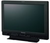
Controls and Their Functions (continued) Rear panel 1 2 3 4 5 6 78 9 SDI (HD/SD) terminal (BNC) IN1 : This is the SDI input terminal (compatible with HD/SD automatic switching). IN2 : This is the SDI input terminal (compatible with HD/SD automatic switching). SWITCHED OUT : This is the active through-out terminal for the SDI input signal being displayed on the screen. * SDI active through-out is only output when [SDI1] or [SDI2] is selected using the [INPUT SELECT] buttons. It is not output when anything other than SDI is selected. This terminal supports embedded audio. When multiple monitors are connected in a daisy chain* pattern using the SDI active through-out, flicker or noise may occur on the screen, depending on the quality of the original signal, length of cables or the number of monitors connected. * Daisy chain connection: This is a connection method for distributing a signal to two or more devices by connecting the through-out terminal of the first device to an input terminal of the second device, the through-output terminal of the second device to an input terminal of the third device, and so on. VIDEO terminal (BNC)*1*2 IN : This is the VIDEO signal (composite signal) input terminal. OUT : This is the input signal through-out terminal. DVI-D terminal (DVI-D) An HDCP compliant DVI-D signal input terminal. YPBPR/RGB terminal (BNC)*1*2 IN : This is the YPBPR/RGB signal input terminal. OUT : This is the input signal through-out terminal. * When using the RGB signal, you can also connect the external synchronizing signal to the SYNC/HD terminal. When using a PC RGB signal, connect the horizontal synchronizing signal to the SYNC/HD terminal, and the vertical synchronizing signal to the VD terminal. VD IN input terminal This is the vertical synchronizing signal (VD) input terminal used when connecting to a PC RGB signal. AUDIO input terminal (pin jack) This is the common audio input terminal for all video input terminals. * SDI input audio is automatically selected by selecting [SDI1] or [SDI2] with [INPUT SELECT]. HEADPHONES output connector (Stereo mini-jack M3) Connect a pair of headphones to monitor the sound. * The sound volume and sound quality will depend on the headphones. Note that plugging in a pair of headphones turns off the speakers. GPI input terminal (D-SUB 9-pin) External control is possible by using a GPI signal. RS232C input terminal (D-SUB 9-pin) External control is possible by using a RS232C signal. *1 Unless a cable is connected to the OUT terminal, the VIDEO IN terminal is automatically terminated at 75Ω. Connecting a cable releases this termination. *2 Since a connection to the through-out terminal releases the 75Ω termination of the unit, the level of the video signal input to the unit may become too large depending on the connected device. 10
-
 1
1 -
2
-
3
-
4
-
 5
5 -
 6
6 -
 7
7 -
 8
8 -
 9
9 -
 10
10 -
 11
11 -
 12
12 -
 13
13 -
 14
14 -
 15
15 -
16
-
17
-
18
-
19
-
20
-
21
-
22
-
23
-
24
-
25
-
26
-
27
-
28
-
29
-
30
-
31
-
32
-
33
-
34
-
35
-
36
-
37
-
38
-
39
-
40
-
41
-
42
-
43
-
44
 |
 |
