Panasonic PT40LC12 Multi-media Display - Page 33
Playing Peripheral Equipment
 |
UPC - 037988974474
View all Panasonic PT40LC12 manuals
Add to My Manuals
Save this manual to your list of manuals |
Page 33 highlights
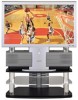
Playing peripheral equipment Confirming connections A video camera uses the Input 3 terminal on the front of the projection display. Example: Connect Input 3 Video camera VCR DVD player To S-video output or video output To audio output This equipment can also be connected to the rear terminals. See Connections for details. Basic Operation Turning the power on and switching input modes 1 Turn the projection display on. TV 2 The input mode changes each time this button is pressed. * LINE 1 * No input mode is displayed for terminals with no equipment connected. * LINE 2 LINE 1: LINE 3 * Signal of source connected to INPUT 1 is displayed. RGB * COMPONENT 2 * COMPONENT 1 LINE 2: Signal of source connected to INPUT 2 is displayed. LINE 3: Signal of source connected to INPUT 3 is displayed. COMPONENT 1: Signal of source connected to COMPONENT VIDEO INPUT 1 is displayed. COMPONENT 2: Signal of source connected to COMPONENT VIDEO INPUT 2 is displayed. RGB: Signal of source connected to PC IN is displayed. 3 Operate the connected equipment. 33
-
 1
1 -
2
-
3
-
4
-
5
-
6
-
7
-
8
-
9
-
10
-
11
-
12
-
13
-
14
-
15
-
16
-
17
-
18
-
19
-
20
-
21
-
22
-
23
-
24
-
25
-
26
-
27
-
 28
28 -
 29
29 -
 30
30 -
 31
31 -
 32
32 -
 33
33 -
 34
34 -
 35
35 -
 36
36 -
 37
37 -
 38
38 -
39
-
40
-
41
-
42
-
43
-
44
-
45
-
46
-
47
-
48
-
49
-
50
-
51
-
52
-
53
-
54
-
55
-
56
-
57
-
58
-
59
-
60
-
61
-
62
-
63
-
64
-
65
-
66
-
67
-
68
-
69
-
70
-
71
-
72
 |
 |
