Panasonic SADP1 SADP1 User Guide - Page 8
Step 3 Television
 |
View all Panasonic SADP1 manuals
Add to My Manuals
Save this manual to your list of manuals |
Page 8 highlights
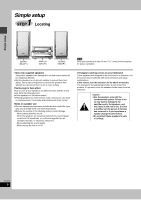
3 STEP Television Video cable Simple setup ∫ Connecting a television with a VIDEO IN terminal Connect directly to your television. Do not connect the unit through a video cassette recorder, because the picture may not be played correctly due to the copy guard. VIDEO IN Television (not included) Video cable (included) AM ANT FM ANT EXT LOOP OPTICAL OUT 75≠ COMPONENT VIDEO OUT PR PB Y S-VIDEO VIDEO OUT OUT L R R L AUX SUBWOOFER OUT HIGH(6≠) LOW(6≠) SPEAKERS (SB-DP1) AC IN ∫ Connecting a television with COMPONENT VIDEO IN terminals COMPONENT VIDEO IN PR PB Y Video cables (not included) COMPONENT VIDEO OUT terminal These terminals can be used for either interlace or progressive output (➡ page 10) and provide a purer picture than the S-VIDEO OUT terminal. Connection using these terminals outputs the color difference signals (PB/PR) and luminance signal (Y) separately in order to achieve high fidelity in reproducing colors. The description of the component video input terminals depends on the television or monitor (e.g. Y/PB/PR, Y/B-Y/R-Y, Y/CB/CR). Connect to terminals of the same color. ≥After making this connection, change the black level for a better picture (➡ page 30, Video-Black Level Control). AM ANT FM ANT EXT LOOP OPTICAL OUT 75≠ COMPONENT VIDEO OUT PR PB Y S-VIDEO VIDEO OUT OUT L AC IN R R L AUX SUBWOOFER OUT HIGH(6≠) LOW(6≠) SPEAKERS (SB-DP1) ∫ Connecting a television with an S-VIDEO IN terminal S-VIDEO IN S-VIDEO OUT terminal The S video terminal achieves a more vivid picture than the VIDEO OUT terminal by separating the chrominance (C) and luminance (Y) signals. (Actual results depend on the television.) RQT6815 8 S-video cable (not included) AM ANT FM ANT EXT LOOP OPTICAL OUT 75≠ COMPONENT VIDEO OUT PR PB Y S-VIDEO VIDEO OUT OUT L R R L AUX SUBWOOFER OUT HIGH(6≠) LOW(6≠) SPEAKERS (SB-DP1) AC IN
-
 1
1 -
2
-
 3
3 -
 4
4 -
 5
5 -
 6
6 -
 7
7 -
 8
8 -
 9
9 -
 10
10 -
 11
11 -
 12
12 -
 13
13 -
14
-
15
-
16
-
17
-
18
-
19
-
20
-
21
-
22
-
23
-
24
-
25
-
26
-
27
-
28
-
29
-
30
-
31
-
32
-
33
-
34
-
35
-
36
-
37
-
38
-
39
-
40
 |
 |
