Panasonic SCHTB550 SCHTB550 User Guide - Page 11
Connect the speaker cables., Drive a screw into the wall.
 |
View all Panasonic SCHTB550 manuals
Add to My Manuals
Save this manual to your list of manuals |
Page 11 highlights
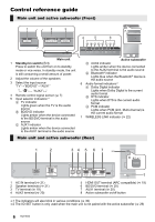
Connect the speaker cables. ≥ Use the "Panasonic" logo to identify the left and right speakers, then connect the cables (as illustrated). White Red Getting started 1 Insert the wire fully. r: White s: Blue line 2 Press into the groove. Push A RED: Right speaker channel (R) B WHITE: Left speaker channel (L) ≥ Insert the wire fully, taking care not to insert beyond the wire insulation. Drive a screw into the wall. ≥ Use the measurements indicated below to identify the screwing positions on the wall. ≥ Leave at least 20 mm (25/32q) of space above and on each side of the speaker to allow enough space for fitting the speaker. ≥ The position on the wall where the screw is to be attached, as well as the screw, should be capable of supporting over 33 kg (72.8 lbs). ≥ Keep the screws out of reach of children to prevent swallowing. C At least 30 mm (1 3/16q) D ‰4.0 mm (5/32q) E ‰7.0 mm to ‰9.4 mm (9/32q to 3/8q) F Wall or pillar G 5.5 mm to 6.5 mm (7/32q to 1/4q) Front view (semi-transparent image) H 326 mm (12 27/32q) I 316 mm (12 7/16q) L Wall mounting hole J 316 mm (12 7/16q) K 26 mm (1 1/16q) 11 RQT9660
-
 1
1 -
2
-
3
-
4
-
5
-
 6
6 -
 7
7 -
 8
8 -
 9
9 -
 10
10 -
 11
11 -
 12
12 -
 13
13 -
 14
14 -
 15
15 -
 16
16 -
17
-
18
-
19
-
20
-
21
-
22
-
23
-
24
-
25
-
26
-
27
-
28
-
29
-
30
-
31
-
32
-
33
-
34
-
35
-
36
 |
 |
