Panasonic WJ-HD616/1000 Installation Guide - Page 22
Rear view
 |
View all Panasonic WJ-HD616/1000 manuals
Add to My Manuals
Save this manual to your list of manuals |
Page 22 highlights
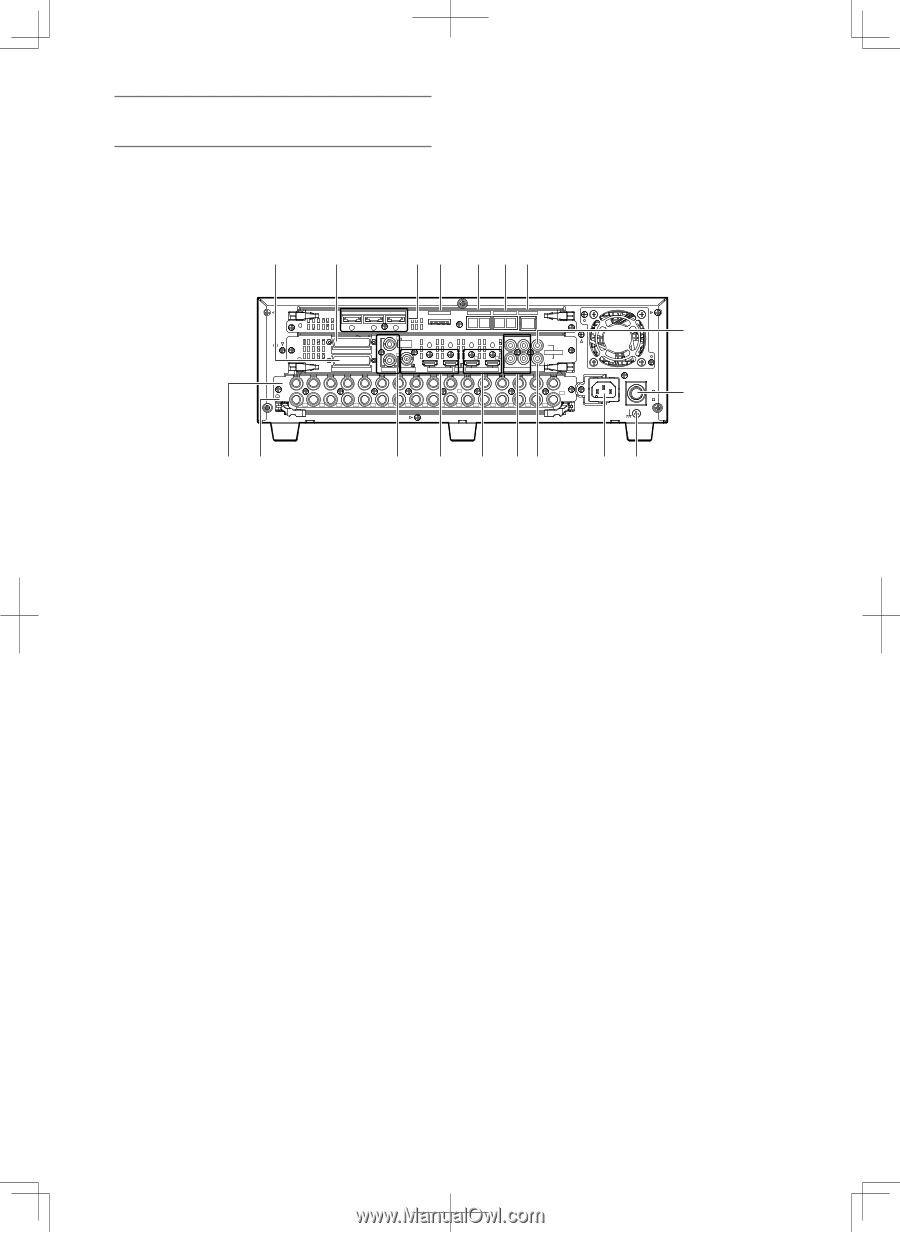
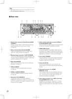
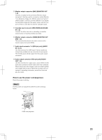
Note: • After attaching the front cover to the recorder, be sure to turn on the power of front cover. ■ Rear view q w er t yu IN OUT EXT STORAGE MODE DATA RS485(CAMERA) 10/100BASE-T 3 2 ALARM ALARM/CONTROL 1 1 MONITOR OUT 2 OUT-CASCADE-IN 12345678 2 2 1 2 1 CASCADE IN OUT MONITOR OUT(HD) 1 3 1 IN CASCADE OUT 4 2 AUDIO AUDIO IN OUT 16 15 14 13 12 11 10 9 8 7 6 5 4 3 2 1 7 1 OUT 16 15 14 13 12 11 10 9 8 7 6 5 4 3 2 VIDEO POWER ON OFF AC IN SIGNAL GND i !0 !2 !3 !4 !5 !6 !7 !8 !1 o q Alarm/Control connector (D-sub 25-pin) [ALARM/ CONTROL] Connect a control switch to control the recorder using an external device such as a buzzer or a lamp. (☞ Page 44) w Alarm connector (D-sub 25-pin) [ALARM] Connect an external device such as a sensor, door switch, etc. to this connector. (☞ Page 48) e External storage connector 1-3 [EXT STORAGE] Connect the optional extension unit (WJ-HDE400) to this connector using the dedicated connection cable provided with the extension unit. (☞ Page 33) r Mode switch [MODE] Determine the operational mode of the recorder using this switch. (☞ Page 51) t DATA port [DATA] Connect a PS·Data compatible device to this port. (☞ Page 35) y RS485 port [RS485/CAMERA] Connect an RS485 combination camera to this port. (☞ Page 42) u Network port [10/100BASE-T] Connect this recorder to a network (10BASE-T/ 100BASE-TX) using this port. When the recorder is connected to a network, it is possible to operate the recorder from a PC via a network. i Audio cascade input/output connector (RCA pin jack) [CASCADE IN, OUT]) Use this connector for audio output from another recorder when it is connected in cascading connection. o SIGNAL GND terminal Connect this terminal to the SIGNAL GND terminals of the devices in the system for signal ground. When operating the recorder and the devices in the system without signal ground, oscillation or noise may be produced. !0 Power button [POWER] Press this button to turn on/off the power of the record- er. When this button is pressed again, the operation is finished and the power is turned off. !1 Power inlet [AC IN] Connect the provided power cord to this inlet. The power plug is a 2-conductor plug with grounding terminal type. !2 Video input connector 1 to 16 (BNC) [VIDEO IN 1 to 16] Connect system cameras and combination cameras to these connectors. When connecting combination cameras, connect them to the video input connector 1-8 (coaxial communication compatible). !3 Video output connector 1 to 16 (BNC, active loop through) [VIDEO OUT 1 to 16] Images input to the video out connectors 1-16 will be output from these connectors. When the power is off, images will not be output to the video output connector 1-16. 22
-
 1
1 -
2
-
3
-
4
-
5
-
6
-
7
-
8
-
9
-
10
-
11
-
12
-
13
-
14
-
15
-
16
-
 17
17 -
 18
18 -
 19
19 -
 20
20 -
 21
21 -
 22
22 -
 23
23 -
 24
24 -
 25
25 -
 26
26 -
 27
27 -
28
-
29
-
30
-
31
-
32
-
33
-
34
-
35
-
36
-
37
-
38
-
39
-
40
-
41
-
42
-
43
-
44
-
45
-
46
-
47
-
48
-
49
-
50
-
51
-
52
-
53
-
54
-
55
-
56
-
57
-
58
-
59
-
60
-
61
-
62
-
63
-
64
-
65
-
66
-
67
-
68
-
69
-
70
-
71
-
72
-
73
-
74
-
75
-
76
-
77
-
78
-
79
-
80
-
81
-
82
-
83
-
84
-
85
-
86
-
87
-
88
-
89
-
90
-
91
-
92
-
93
-
94
-
95
-
96
-
97
-
98
-
99
-
100
-
101
-
102
-
103
-
104
-
105
-
106
-
107
-
108
-
109
-
110
-
111
-
112
-
113
-
114
-
115
-
116
-
117
-
118
-
119
-
120
-
121
-
122
-
123
-
124
-
125
-
126
-
127
-
128
-
129
-
130
-
131
-
132
-
133
-
134
-
135
-
136
-
137
-
138
-
139
-
140
-
141
-
142
-
143
-
144
-
145
-
146
-
147
-
148
-
149
-
150
-
151
-
152
-
153
-
154
-
155
-
156
 |
 |