Panasonic WJ-HD616/1000 Installation Guide - Page 49
Alarm connection
 |
View all Panasonic WJ-HD616/1000 manuals
Add to My Manuals
Save this manual to your list of manuals |
Page 49 highlights
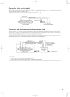
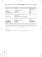
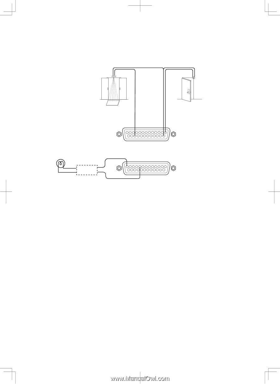
Alarm connection When a signal is supplied to the alarm input terminals 1 - 16 (pin nos. 1 - 8, 15 - 22 of the ALARM connector), recording and displaying of images from the cameras will be performed according to the settings. When an alarm device such as a buzzer, a lamp, etc., is installed outside, connect them to the alarm output terminals (pin nos. 9 - 12, 23 - 25 of the ALARM connector or pin nos. 1 - 9 of the ALARM/CONTROL connector). Sensor Door security switch (Alarm input 16) (Signal ground) (Alarm input 1) 22 14 1 Alarm Alarming device (Signal ground) 13 Relays, etc.* * Attached when necessary (Alarm output16) 9 ALARM/CONTROL 49
-
 1
1 -
2
-
3
-
4
-
5
-
6
-
7
-
8
-
9
-
10
-
11
-
12
-
13
-
14
-
15
-
16
-
17
-
18
-
19
-
20
-
21
-
22
-
23
-
24
-
25
-
26
-
27
-
28
-
29
-
30
-
31
-
32
-
33
-
34
-
35
-
36
-
37
-
38
-
39
-
40
-
41
-
42
-
43
-
 44
44 -
 45
45 -
 46
46 -
 47
47 -
 48
48 -
 49
49 -
 50
50 -
 51
51 -
 52
52 -
 53
53 -
 54
54 -
55
-
56
-
57
-
58
-
59
-
60
-
61
-
62
-
63
-
64
-
65
-
66
-
67
-
68
-
69
-
70
-
71
-
72
-
73
-
74
-
75
-
76
-
77
-
78
-
79
-
80
-
81
-
82
-
83
-
84
-
85
-
86
-
87
-
88
-
89
-
90
-
91
-
92
-
93
-
94
-
95
-
96
-
97
-
98
-
99
-
100
-
101
-
102
-
103
-
104
-
105
-
106
-
107
-
108
-
109
-
110
-
111
-
112
-
113
-
114
-
115
-
116
-
117
-
118
-
119
-
120
-
121
-
122
-
123
-
124
-
125
-
126
-
127
-
128
-
129
-
130
-
131
-
132
-
133
-
134
-
135
-
136
-
137
-
138
-
139
-
140
-
141
-
142
-
143
-
144
-
145
-
146
-
147
-
148
-
149
-
150
-
151
-
152
-
153
-
154
-
155
-
156
 |
 |
49
Alarm connection
When a signal is supplied to the alarm input terminals 1 - 16 (pin nos. 1 - 8, 15 - 22 of the ALARM connector), recording and dis-
playing of images from the cameras will be performed according to the settings.
When an alarm device such as a buzzer, a lamp, etc., is installed outside, connect them to the alarm output terminals (pin nos. 9
- 12, 23 - 25 of the ALARM connector or pin nos. 1 - 9 of the ALARM/CONTROL connector).
9
13
22
1
14
Sensor
(Alarm input 16)
(Signal ground)
(Alarm input 1)
Door security
switch
Alarm
Alarming device
ALARM/CONTROL
(Alarm output16)
(Signal ground)
* Attached when necessary
Relays, etc.*