Poulan 1994-04 User Manual - Page 7
Handlebar
 |
View all Poulan 1994-04 manuals
Add to My Manuals
Save this manual to your list of manuals |
Page 7 highlights
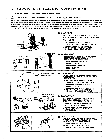
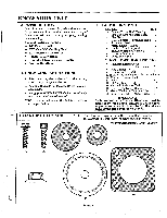
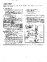
C. HANDLEBAR A WARNING The handlebar mounting block must be placed above the point of the arrow on the safety labels. The handlebar is a barrier to keep the blade away from the operator's feet. 1. Position the mounting block on the tube above the arrow on the safety labels. Figure 3 . 2. Place one of the covers under the tube. Figure 3 . Attach the cover to the mounting block with 2 screws "B."; finger tighten only. 3. Align the handlebar with the straight barrier portion to the left and the curved portion to the right as shown in Figure 3 . 4. Position the short, straight section of the handlebar in the mounting block. 5. Place the other cover on top of the tube. Figure 3 . Attach the cover to the mounting block with 2 screws "B."; finger tighten only. D. FOR BLADE USE A DANGER The metal shield and metal handlebar must be properly installed on the tool anytime the tool is used with the blade. The forward tip on the metal shield helps to reduce the occurrence of blade thrust which can cause serious injury such as amputation to the operator or bystanders. A WARNING Failure to install the shield in the position shown in Figures 4 and 5 can result in serious injury to the operator. The length of the shield must be aligned with the length of the drive shaft housing. Direct widest part of shield toward the engine. NOTF4 If your unit is equipped as a line trimmer, re move the plastic shield, grass washer, and trimmer head before installing the metal shield and blade. Be sure to store parts for future use. 1. Position retention plate "G." on the underside of the metal shield and align screw holes. Make sure flat side of plate is against the shield. 2. Hold retention plate "G." in position and place the metal shield under the bearing housing. Align screw holes. Figure 4 . 3. Insert screws "B."(one at a time) through bearing housing, shield, and retention plate "G." Figure 4 . 4. Tighten screws evenly & securely with hex wrench. 5. Remove packing cover from arbor shaft if so equipped. 6. Install the blade over arbor shaft, making sure the hole in the center of the blade is fitted around the raised center step on the dust cup. Figure 4 . 7. Install washer "C.", cupped washer "D.", and nut "K" Figure 4 . Be sure cupped washer "D." is installed as shown in the lower inset in Figure 4 . 8. Align the hole in the dust cup with the hole in the side of the bearing housing by turning the dust cup. Figure 4 (upper inset). 9. Insert large hex wrench (provided) into the aligned holes to keep arbor shaft from turning. Figure 4 . A WARNING The barrier portion of the handlebar must be installed as shown in Figure 3 to provide a barrier between operator and spinning blade. Curved Portion Grip Screw B. Mounting Block Screw B. R 14/ Cover Figure 3 Barrier Portion Cover Short, Straight Portion -0- Safety Labels 10. Tighten nut "E." firmly with a wrench while holding hex wrench in position. 11. Remove the hex wrench. 12. Turn blade by hand. If the blade binds against the shield, the blade is not centered. Reinstall the blade. 13. Proceed to "Shoulder Strap" instructions. NOTE: To remove the blade, insert the large hex wrench into aligned holes. Un-thread the hex flange nut and remove parts. Be sure to store the retention plate, hex flange nut, beveled washer, flat washer, shield screws, and metal shield with the blade for future use. Hex Wrench in Bearing Housing Clam Screw B.* Dust Cup Arbor Shaft Widest Portion of Shield* Toward Engine Retention Plate G.* Cupped Side Toward Washer D.* Blade $ Figure 4 Blade* Washer C.* Washer D.* (see inset) "`"--- Nut E.* A WARNING Parts noted with * are critical and must be supplied by Weed Eater. Failure to use proper parts can cause the blade to fly off and seriously hurt you or others.
-
 1
1 -
 2
2 -
 3
3 -
 4
4 -
 5
5 -
 6
6 -
 7
7 -
 8
8 -
 9
9 -
 10
10 -
 11
11 -
 12
12 -
13
-
14
-
15
-
16
-
17
-
18
-
19
-
20
-
21
-
22
-
23
-
24
 |
 |
