ProForm 7.0 Re Elliptical English Manual - Page 6
Assembly - 70
 |
View all ProForm 7.0 Re Elliptical manuals
Add to My Manuals
Save this manual to your list of manuals |
Page 6 highlights
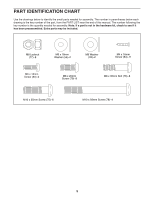
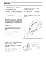
ASSEMBLY •• To hire an authorized service technician to assemble the elliptical, call 1-800-445-2480. •• Assembly requires two persons. •• Place all parts in a cleared area and remove the packing materials. Do not dispose of the packing materials until you nish assembly. •• Left parts are marked “"L”" or “"Left”" and right parts are marked “"R”" or “"Right.”" •• To identify small parts, see page 5. •• In addition to the included tool(s), assembly requires the following tools: one Phillips screwdriver one rubber mallet Assembly may be easier if you have a set of wrenches. To avoid damaging parts, do not use power tools. 1. With the help of a second person, place some of the packing materials (not shown) under the rear 1 of the Frame (1). Have the second person hold the Frame to prevent it from tipping while you complete this step. Tighten a Leveling Foot (47) into the underside of the Frame (1). Identify the Rear Stabilizer (70), which does not have wheels, and orient it as indicated by the sticker. Attach the Rear Stabilizer (70) to the Frame (1) 70 with two M10 x 93mm Screws (78). Remove the packing materials from under the rear of the Frame (1). 78 47 1 2. With the help of a second person, place some of the packing materials (not shown) under the 2 front of the Frame (1). Have the second per- son hold the Frame to prevent it from tipping while you complete this step. Orient the Front Stabilizer (73) as indicated by the sticker. Attach the Front Stabilizer (73) to the Frame (1) with two M10 x 93mm Screws (78). Remove the packing materials from under the front of the Frame (1). 73 78 1 6
-
 1
1 -
 2
2 -
 3
3 -
 4
4 -
 5
5 -
 6
6 -
 7
7 -
 8
8 -
 9
9 -
 10
10 -
 11
11 -
 12
12 -
13
-
14
-
15
-
16
-
17
-
18
-
19
-
20
-
21
-
22
-
23
-
24
-
25
-
26
-
27
-
28
 |
 |
