ProForm 755 Crosstrainer Treadmill English Manual - Page 6
Assembly - treadmill
 |
View all ProForm 755 Crosstrainer Treadmill manuals
Add to My Manuals
Save this manual to your list of manuals |
Page 6 highlights
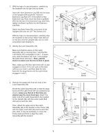
ASSEM2 1B/2"LBoYlt (37)-2 Star Washer (106)-4 Washer (38)-4 3/4" Screw (2)-6 To hire an authorized service technician to assemble the treadmill, call 1-800-445-2480. Assembly requires two p3er1s/2o"nBs.oSlt e(4t 5th)-e4treadmill in a cleared area and rWemheoevleNaullt p(3a2c)k-in2g materials. Do not dispose of the packing materials until assembly is completed. Note: The underside of the treadmill walking belt is coated with high-performance lubricant. During shipping, a small amount of lubricant may be transferred to the top of the walking belt or the shipping carton. This does not affect treadmill performance. If there is lubHraicnadnrtaoilnBolt (64)-4 top of the walking belt, simply wipe off the lubricant with a soft cloth and a mild, non-abrasive cleaner. Assembly require1s" Ttheek Sinccrleuwde(8d3h)-e4x key and your own Phillips screwdriver least 6 in. (16 cm) long, wire cutters , and an adjustable wrench with a shaft at . Sta(r8W4)a-Utishs2shetehekertehqyeundaurnamtwitbyiennrgeEosexfbdtteehenledoswpfioantrrota,LisdfersegoenmmBtiofbtyhlltyet(h.9PNe6Ao)a-Rtse4sT:eILmfISablTpy anhreataridrswWthnaheoreetee.innlTdNhtohuefetnt(hhu1ima3sr)bm-de2warnainureaplka. irTte,hncethhneeuscmeksbtEeobrxestaleoefntweesriiefotahnitceLhispedagprrareBewnoaitlnthttge(a9sci6seh)se-d4 to one of the parts to be assembled. To avoid damaging plastic parts, do not use power tools for assembly. Extra hardware may be included. 3/4" Tek Screw (22)-4 Ground Screw (33)-1 Screw (3)-9 Upper Latch Bolt (50)-1 Extension Leg Nut (67)-4 Latch Nut (30)-2 Star Washer (8)-4 1. Make sure that the power cord is unplugged. 1 With the help of a second person, carefully tip the treadmill onto its left side as shown. Insert an Extension Leg (89) into the base of the Uprights (84) as shown. Hold two Extension Leg Nuts (67) in the bottom of the Extension Leg. Next, insert two Base Leg Bolts (65) into the top of the Extension Leg, and firmly tighten the Base Leg Bolts into the Extension Leg Nuts. Attach two Base Pads (82) to the base of the Uprights (84) with two 3/4" Tek Screws (22). Lower Latch Bolt (39)-1 Base Leg Bolt (65)-4 Handrail Bolt (64)-4 84 65 82 22 89 67 82 22 6
-
 1
1 -
 2
2 -
 3
3 -
 4
4 -
 5
5 -
 6
6 -
 7
7 -
 8
8 -
 9
9 -
 10
10 -
 11
11 -
 12
12 -
13
-
14
-
15
-
16
-
17
-
18
-
19
-
20
-
21
-
22
-
23
-
24
-
25
-
26
-
27
-
28
 |
 |
