ProForm 850 Ci English Manual
ProForm 850 Ci Manual
 |
View all ProForm 850 Ci manuals
Add to My Manuals
Save this manual to your list of manuals |
ProForm 850 Ci manual content summary:
- ProForm 850 Ci | English Manual - Page 1
If you have questions, or find there are missing or damaged parts, we will guarantee you complete satisfaction through direct assistance from CAUTION! Read all safety precautions and instructions in this manual before using this equipment. Save this manual for future reference. 0 O 0 PATENT - ProForm 850 Ci | English Manual - Page 2
BEGIN ASSEMBLY ADJUSTING THE CROSS TRAINING SYSTEM TROUBLE-SHOWING AND MAINTENANCE ORDERING REPLACEMENT PARTS LIMITED VVARANTY 4n 441.4 • ? of 35 or persons with pre-existing health problems. Read all Instructions before using. PROFORM assumes no responsibility for personal injury or property - ProForm 850 Ci | English Manual - Page 3
for selecting the PROFORM® 850 CI cross training system. The 850 CI offers an impressive 850 CI will help you to achieve the specific results you want. For your safety and benefit, read this manual carefully before using the 850 Cl. If you have additional questions, please call our Customer Service - ProForm 850 Ci | English Manual - Page 4
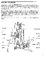
. Read each step and examine each drawing carefully. Make sure that all parts are oriented as shown in the drawings. Refer to the PART IDENTIFICATION CHART accompanying this owner's manual for help identifying the small parts used in assembly. The following tools (not included) are required: two - ProForm 850 Ci | English Manual - Page 5
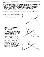
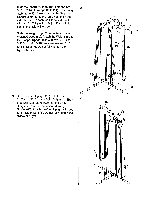
the 2" x 3" Cap (59) into the Frame Top 5 (79). Attach the Frame Top (79) to the Leg Press Upright (87) with Guides (80)-there are holes near the upper ends of the Weight Guides. Slide the four Bumpers (17) onto the lower ends of the Weight Guides. Insert the lower ends of the Weight Guides - ProForm 850 Ci | English Manual - Page 6
the Stepper Upright with two 5/16' Nylock Nuts (1). Do not fully tighten the Nylock Nuts yet. Slide the Weight Top (75) onto the indicated Weight Guides (80). Attach the Weight Top to the Stepper Upright (84) with two 5/16" x 2 3/4" Bolts (12), 5/16" Washers (4) and 5/16" Nylock Nuts (1). Do not - ProForm 850 Ci | English Manual - Page 7
sure that the Cable is pointed in the direction shown. 11. Attach two of the Weight Guides (80) to the 11 Weight Top (75) with 5/16" x 2 1/2" Bolts (9) and 5/16" Nylock Nuts (1). Attach two of the Weight Guides (80) to the Cam Upright (85) with 5/16" x 2 1/2" Bolts (9) and 5/16" Nylock Nuts - ProForm 850 Ci | English Manual - Page 8
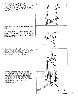
14. Grease the lower axles on the Stepper Upright (84). Press two Square Bushings (104) into the Right Pedal (101). Slide the Pedal onto the right axle. Make sure that the Pedal Is on the correct side-the slotted bracket must be oriented as shown. Tap a 1" Retainer (94) and 1" Plastic Cap (95) onto - ProForm 850 Ci | English Manual - Page 9
Arm Bushings (67) into the Moment Arm (69). Align the Moment Arm with the indicated hole in the Frame Top (79). Insert the 1/2" Axle (68) through the Moment Arm and the Frame Top. Tap a 1/2' Retainer (64) and 1/2' Plastic Cap (65) onto the other end of the Axle. Make sure that the teeth - ProForm 850 Ci | English Manual - Page 10
22. Attach a 6" Plate (27) to the Small Seat 22 Frame (52) with a 1/4' x 2 1/4' Carriage Bolt (25), 1/4" Washer (5) and 1/4" Nylock Nut (3). Attach the Small Seat (53) to the Small Seat Frame (52) with a 1/4" x 2' Screw (11) and 1/4" Washer (5). Do not tighten the Screw yet. (The Small Seat is - ProForm 850 Ci | English Manual - Page 11
2' Bolt (61) and a 5/16' Nylock Nut (1). Lay the 110' Cable (96) over a 3' Pulley (7) as shown. Attach the Pulley to the Short 'U' Bracket (60) with a 3/8' x 1 3/4' Bolt (6) and 3/8' Nylock Nut (1). 27. Press two 1 3/4" x 1 3/4' Caps (34) into the Leg Press Frame (88). Attach the Leg Press Frame (88 - ProForm 850 Ci | English Manual - Page 12
Attach the Large Seat (109) to the 6" Plate (27) with two 1/4" x 3/4" Screws (8). Tighten all three Screws attaching the Large Seat. 33. Press two Weight Guides (58) into each of 33 the twenty Weights (105) as shown. IIIII. ..11 110 - 25-i 27 --- •-• 1091 8144 /0 ( - 3 11 58 105 U . 58 - ProForm 850 Ci | English Manual - Page 13
Weights (105) onto each pair of 34 Weight Guides (8O) by tipping the Weights as shown. Make sure that all of the Weights are turned so the pin grooves are downward, and are on the indicated sides. Press a Weight Sleeve (57) into the Top Weight (105) on each stack of Weights. Pin - ProForm 850 Ci | English Manual - Page 14
20 1p- 113 40 2 1 98 55 85 38. Lay the 195" Cable (98) over a 3" Pulley (7). Attach the Pulley to the indicated bracket on the Frame Top (79) with a 3/8" x 1 3/4" Bolt (6) and 3/8' Nylock Nut (2). 38 79 98 NO C 7 39. Insert the 195" Cable (98) through the other 39 Long "U" Bracket (19). Lay - ProForm 850 Ci | English Manual - Page 15
40. Find the upper end of the other Weight Tube (78)-there is a single hole near the upper 40 98 end. Attach the 195' Cable (98) to the upper end of the Weight Tube with a 5/16' x 1 1/2' 1 Bolt (54) and 5/16' Nylock Nut (1). / 77 Press a Weight Tube Cap (77) into the lower 78 end of the - ProForm 850 Ci | English Manual - Page 16
43. Route the 137' Cable (97) under the indicat- 43 ed 3" Pulley (7) on the Leg Press Upright (87). Insert the threaded end of the 137' Cable (97) into the indicated Long "Li' Bracket (19). Thread a 5/16" Nylock Nut (1) onto the end of 1 the Cable. The end of the Cable should pro- trude - ProForm 850 Ci | English Manual - Page 17
46. Attach the other three Cam Sleeve Bushings (35) to the Cam Sleeve (44) as shown with 46 3/8" x 3 3/4' Bolts (33) and 3/8" Nylock Nuts (2). Z •• I 33 . 2 0 5 - t) 44 a 33 35 ,,, I ,,, i / III ii 47. Attach a 3" Pulley (7) to the Cam (43) with a 47 3/8" x 1 3/4' Bolt (6) and - ProForm 850 Ci | English Manual - Page 18
50. Slide the Cam Arm (50) onto the Cam (43). 50 Tap a 3/4' Retainer (63) and 3/4' Plastic Cap - • (66) onto the shaft. Make sure that the teeth • of the Retainer bend toward the Plastic Cap. 66fi3 . -- 43 50 51. Pull the Cam Knob (38) outward and pivot the 51 Cam Arm (50) until the Knob - ProForm 850 Ci | English Manual - Page 19
..." I CI I ' SPEED LINK' Note: The words WNW 'FAST' must be at this end. "LEG PRESS" c:=Z=Iorl 55. Make sure that all parts are properly tightened. The use of all remaining parts will be explained in ADJUSTING THE CROSS TRAINING SYSTEM, beginning on page 20 of this owner's manual problem before - ProForm 850 Ci | English Manual - Page 20
The instructions below describe how each part of the cross training system can be adjusted. See the EXERCISE GUIDE accompanying this owne►'s manual to see 10 pounds. Insert a 7" "L" Pin wiTab (56) under the top Weight (105) on each weight stack. Turn the ends of the Pins downward. Always keep a Pin - ProForm 850 Ci | English Manual - Page 21
. CHANGING THE HEIGHT OF THE CAM SLEEVE The height of the Cam Sleeve (44) must be changed for different exercises. To change the height, first support the weight of the Cam Sleeve with one hand. Remove the 6 3/4" "L" Pin (49), slide the Cam Sleeve up or down, and reinsert the 6 3/4" "L" Pin through - ProForm 850 Ci | English Manual - Page 22
USING THE ARMS IN THE PRESS MODE To do the Bench Press or Military Press exercises, the Arms (70, 71) should be changed to the press mode. Make sure the 5" "L" Pin (not shown) is removed from the Moment Arm (69). Insert the two Arm "L" Pins (62) into the Moment Arm (69) and the Arms to lock the Arms - ProForm 850 Ci | English Manual - Page 23
TROUBLE-SHOOTING AND MAINTENANCE Inspect and tighten all parts each time you use the cross training system. Replace any worn parts immediately. The cross training system can be cleaned replaced. See the back cover of this owner's manual for information about ordering replacement parts. B 19 97 23 - ProForm 850 Ci | English Manual - Page 24
of the product (PROFORM® 850 CI cross training system).. 3. The SERIAL NUMBER of the product (see the front cover of this manual). 4. The KEY NUMBER and DESCRIPTION of the part(s) from the PART LIST/EXPLODED DRAWING accompanying this owner's manual. LIMITED WARRANTY Proform Fitness Products, Inc
-
 1
1 -
 2
2 -
 3
3 -
 4
4 -
 5
5 -
 6
6 -
 7
7 -
8
-
9
-
10
-
11
-
12
-
13
-
14
-
15
-
16
-
17
-
18
-
19
-
20
-
21
-
22
-
23
-
24
 |
 |
PRO•FORM
®
Model
Serial
No.
PF804030
No.
Serial
Number
Decal
QUESTIONS?
As
a
manufacturer,
we
are
committed
to
providing
you
complete
customer
satisfac-
tion.
If
you
have
questions,
or
find
there
are
missing
or
damaged
parts,
we
will
guarantee
you
complete
satisfaction
through
direct
assistance
from
our
factory.
TO
AVOID
UNNECESSARY
DELAYS,
PLEASE
CALL
DIRECT
TO
OUR
TOLL
-FREE
CUSTOMER
HOT
LINE.
The
trained
technicians
on
our
customer
hot
line
will
provide
immediate
assis-
tance,
free
of
charge
to
you.
CUSTOMER
HOT
LINE:
1-800-999-3756
Mon.
—Fri.,
6
a.m.-6
p.m.
MST
CAUTION!
Read
all
safety
precautions
and
instructions
in
this
manual
before
using
this
equipment.
Save
this
manual
for
future
reference.
PATENT
PENDING
TM
C
CAST
IRON
VP
RESISTANCE
Cabm'ef
Com
0
0
O
OWNER'S
MANUAL