ProForm 850 Ci English Manual - Page 11
ProForm 850 Ci Manual
 |
View all ProForm 850 Ci manuals
Add to My Manuals
Save this manual to your list of manuals |
Page 11 highlights
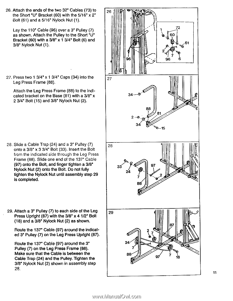
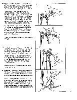
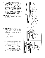
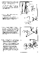
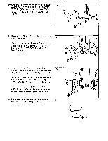
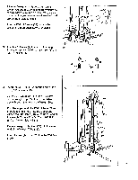
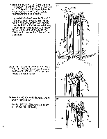
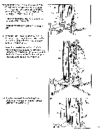
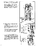
26. Attach the ends of the two 32' Cables (73) to the Short 'U' Bracket (60) with the 5/16' x 2' Bolt (61) and a 5/16' Nylock Nut (1). Lay the 110' Cable (96) over a 3' Pulley (7) as shown. Attach the Pulley to the Short 'U' Bracket (60) with a 3/8' x 1 3/4' Bolt (6) and 3/8' Nylock Nut (1). 27. Press two 1 3/4" x 1 3/4' Caps (34) into the Leg Press Frame (88). Attach the Leg Press Frame (88) to the indicated bracket on the Base (81) with a 3/8" x 2 3/4" Bolt (15) and 3/8' Nylock Nut (2). 26 I -.-- ..... c !. . 96 --' 1 72 . i. . vt 0 i.t 61 27' 7 6 8 27 34-47 88 81 2--a , 34 1.5 28. Slide a Cable Trap (24) and a 3' Pulley (7) onto a 3/8' x 3 3/4' Bolt (33). Insert the Bolt from the indicated side through the Leg Press Frame (88). Slide one end of the 137" Cable (97) onto the Bolt, and finger tighten a 3/8' Nylock Nut (2) onto the Bolt. Do not fully tighten the Nylock Nut until assembly step 29 is completed. 28 33 7 24 , 97 .. _ 7 _ 88 29. Attach a 3' Pulley (7) to each side of the Leg 29 Press Upright (87) with the 3/8' x 4 1/2' Bolt (18) and a 3/8' Nylock Nut (2) as shown. Route the 137" Cable (97) around the indicated 3" Pulley (7) on the Leg Press Upright (87). i ,, 87 / 2\ .i., Route the 137" Cable (97) around the 3' 24 Pulley (7) on the Leg Press Frame (88). Make sure that the Cable is between the Cable Trap (24) and the Pulley. Tighten the 88/. 97 7 18 3/8" Nylock Nut (2) shown in assembly step 28. 11
-
 1
1 -
2
-
3
-
4
-
5
-
 6
6 -
 7
7 -
 8
8 -
 9
9 -
 10
10 -
 11
11 -
 12
12 -
 13
13 -
 14
14 -
 15
15 -
 16
16 -
17
-
18
-
19
-
20
-
21
-
22
-
23
-
24
 |
 |