ProForm 850 Ci English Manual - Page 18
ProForm 850 Ci Manual
 |
View all ProForm 850 Ci manuals
Add to My Manuals
Save this manual to your list of manuals |
Page 18 highlights
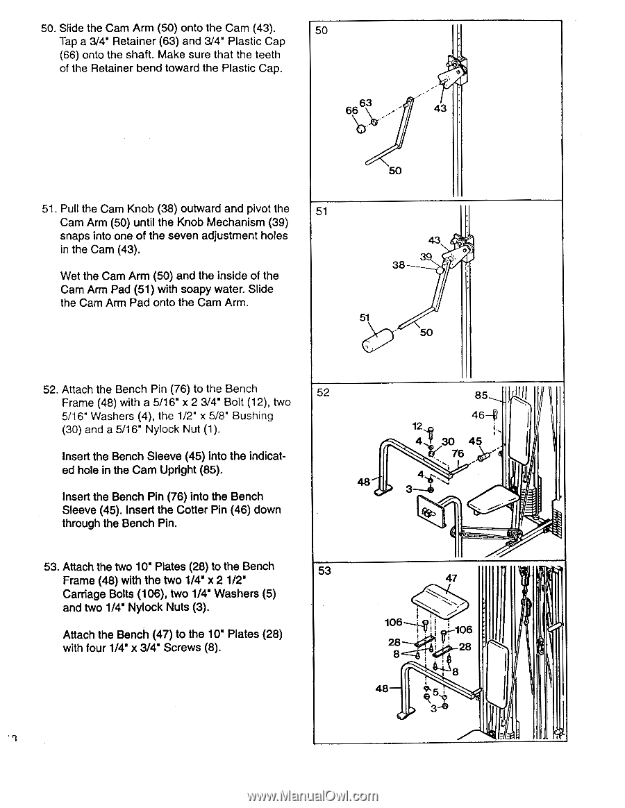
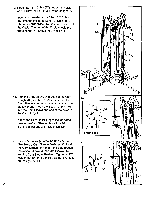
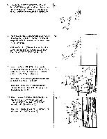
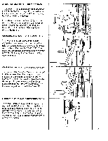
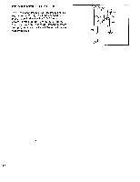
50. Slide the Cam Arm (50) onto the Cam (43). 50 Tap a 3/4' Retainer (63) and 3/4' Plastic Cap - • (66) onto the shaft. Make sure that the teeth • of the Retainer bend toward the Plastic Cap. 66fi3 . -- 43 50 51. Pull the Cam Knob (38) outward and pivot the 51 Cam Arm (50) until the Knob Mechanism (39) snaps into one of the seven adjustment holes in the Cam (43). Wet the Cam Arm (50) and the inside of the Cam Arm Pad (51) with soapy water. Slide the Cam Arm Pad onto the Cam Arm. 43 a• 39 ''. 38 • 51 ' 50 .., 52. Attach the Bench Pin (76) to the Bench 52 Frame (48) with a 5/16" x 2 3/41 Bolt (12), two 5/16" Washers (4), the 1/2" x 5/8" Bushing (30) and a 5/16" Nylock Nut (1). Insert the Bench Sleeve (45) into the indicated hole in the Cam Upright (85). 48 Insert the Bench Pin (76) into the Bench Sleeve (45). Insert the Cotter Pin (46) down through the Bench Pin. 85 illll 46-1 12 I 4 .,, 45 la.r,. 76 ' 1 ... 3 :-... N „- -- - 53. Attach the two 10" Plates (28) to the Bench 53 Frame (48) with the two 1/4" x 2 1/2" Carriage Bolts (106), two 1/4" Washers (5) and two 1/4" Nylock Nuts (3). Attach the Bench (47) to the 10" Plates (28) with four 1/4" x 3/4' Screws (8). 41 47 106--tv iI i 106 28--.14* V- 8-= -44! rAk!i*4"8 • ;--18 48 iix. ' 4k ''' 3-0 • i I I
-
 1
1 -
2
-
3
-
4
-
5
-
6
-
7
-
8
-
9
-
10
-
11
-
12
-
 13
13 -
 14
14 -
 15
15 -
 16
16 -
 17
17 -
 18
18 -
 19
19 -
 20
20 -
 21
21 -
 22
22 -
 23
23 -
24
 |
 |