ProForm G720 Bench Uk Manual - Page 7
Tighten the M10 Nylon Locknuts 11 used
 |
View all ProForm G720 Bench manuals
Add to My Manuals
Save this manual to your list of manuals |
Page 7 highlights
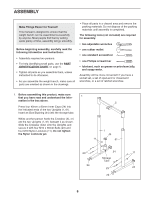
2. Press the Foot Plate (4) onto the bottom of the Front Leg (3). Attach the Front Leg (3) to the Bench Frame (5) with two M10 x 95mm Bolts (56), the Support Plate (62), and two M10 Nylon Locknuts (11). Do not tighten the Nylon Locknuts yet. 2 62 56 4 11 5 11 3 3. Lubricate an M10 x 80mm Bolt (13) with grease. Attach the Bench Frame (5) to the upper set of holes in the bracket on the Crossbar (2) with the Bolt, two M10 Washers (6), and an M10 Nylon Locknut (11). Do not overtighten the Nylon Locknut; the Bench Frame must be able to pivot easily. Secure the Bench Frame (5) to the Crossbar (2) with an M10 x 65mm Adjustment Knob (54) as shown. Insert the Ring Pin (31) into the bracket on the Crossbar. Tighten the M10 Nylon Locknuts (11) used in steps 1 and 2. 4. Identify the Left and Right Backrest Frames (14, 15) by the position of the adjustment tubes, and orient them as shown. Tap two 25mm Square Inner Caps (10) into the ends of each Backrest Frame. Tap a 25mm x 50mm Inner Cap (16) into the bottom of each adjustment tube. 3 Lubricate 6 13 5 54 2 6 Bracket 31 11 4 10 15 14 5. Attach the Backrest (12) to the Left and Right Backrest Frames (14, 15) with four M6 x 38mm Screws (39) and four M6 Washers (38). Do not tighten the Screws yet. 10 16 5 12 15 39 7 Adjustment Tubes 14 38 39 38
-
 1
1 -
 2
2 -
 3
3 -
 4
4 -
 5
5 -
 6
6 -
 7
7 -
 8
8 -
 9
9 -
 10
10 -
 11
11 -
 12
12 -
13
-
14
-
15
-
16
-
17
-
18
-
19
-
20
 |
 |
