ProForm Xp 185 U Bike Canadian English Manual - Page 6
mm Button Screws 33 and two M10 Split
 |
View all ProForm Xp 185 U Bike manuals
Add to My Manuals
Save this manual to your list of manuals |
Page 6 highlights
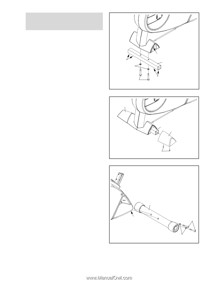
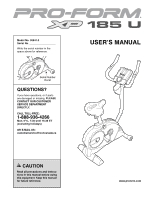
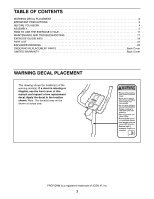
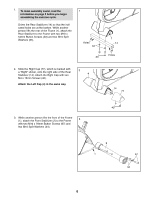
1. To make assembly easier, read the information on page 5 before you begin assembling the exercise cycle. Orient the Rear Stabilizer (14) so that the indicated holes are at the bottom. While another person lifts the rear of the Frame (1), attach the Rear Stabilizer to the Frame with two M10 x 54mm Button Screws (33) and two M10 Split Washers (34). 1 Holes 34 33 1 14 Holes 2. Slide the Right Cap (77), which is marked with a "Right" sticker, onto the right side of the Rear Stabilizer (14). Attach the Right Cap with two 2 4 M4 x 16mm Screws (40). Attach the Left Cap (4) in the same way. 14 77 40 3. While another person lifts the front of the Frame (1), attach the Front Stabilizer (2) to the Frame 3 with two M10 x 78mm Button Screws (67) and two M10 Split Washers (34). 2 1 67 34 6
-
 1
1 -
 2
2 -
 3
3 -
 4
4 -
 5
5 -
 6
6 -
 7
7 -
 8
8 -
 9
9 -
 10
10 -
 11
11 -
 12
12 -
13
-
14
-
15
-
16
-
17
-
18
-
19
-
20
-
21
-
22
-
23
-
24
 |
 |