Ryobi P552 Manual 1 - Page 12
Mounting Holes, Warning, Blade Wrench, Dust Bag
 |
View all Ryobi P552 manuals
Add to My Manuals
Save this manual to your list of manuals |
Page 12 highlights
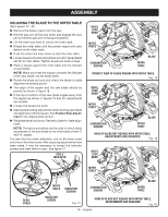
ASSEMBLY MOUNTING HOLES See Figure 8. WARNING: Before starting any cutting operation, clamp or bolt your miter saw to a workbench or an approved miter saw stand. If a miter saw stand is used, read operator's manual and follow the instructions for the miter saw stand. Never operate your miter saw on the floor or in a crouched position. Failure to heed this warning can result in serious personal injury. The compound miter saw should be mounted to a firm supporting surface such as a workbench, mounting board, or miter saw stand. The saw base has four mounting holes. If using bolts, they should be of sufficient length to accommodate the saw base, lock washers, hex nuts, and the thickness of the workbench or other mounting surface. Tighten all bolts or screws securely. The hole pattern for mounting to a workbench is shown in figure 8. Carefully check the workbench after mounting to make sure that no movement can occur during use. If any tipping, sliding, or walking is noted, secure the workbench to the floor before operating. BLADE WRENCH See Figure 9. A blade wrench is included with this saw. One end of the wrench is a phillips screwdriver and the other end is a hex key. Use the hex key end when installing or removing blade and the phillips end when removing or loosening screws. A storage area for the blade wrench is located on the back of the left miter fence. DUST BAG See Figure 9. A dust bag is provided for use on this miter saw. It fits over the exhaust port on the upper blade guard. To install, squeeze the two metal clips to open the mouth of the bag and slide it on the exhaust port. Release the clips. The metal ring in the bag should lock in between the grooves on the exhaust port. To remove the dust bag for emptying, simply reverse the above procedure. DUST BAG EXHAUST PORT BLADE WRENCH Fig. 9 TRACE HOLES AT THESE LOCATIONS FOR HOLE PATTERN 45 31.6 30 22.5 15 0 22.5 30 31.6 15 BASE 12 - English 45 TRACE HOLES AT THESE LOCATIONS FOR HOLE PATTERN MOUNTING SURFACE Fig. 8
-
 1
1 -
2
-
3
-
4
-
5
-
6
-
 7
7 -
 8
8 -
 9
9 -
 10
10 -
 11
11 -
 12
12 -
 13
13 -
 14
14 -
 15
15 -
 16
16 -
 17
17 -
18
-
19
-
20
-
21
-
22
-
23
-
24
-
25
-
26
-
27
-
28
-
29
-
30
-
31
-
32
-
33
-
34
-
35
-
36
-
37
-
38
-
39
-
40
-
41
-
42
-
43
-
44
-
45
-
46
-
47
-
48
-
49
-
50
-
51
-
52
-
53
-
54
-
55
-
56
-
57
-
58
-
59
-
60
-
61
-
62
-
63
-
64
-
65
-
66
-
67
-
68
-
69
-
70
-
71
-
72
-
73
-
74
-
75
-
76
-
77
-
78
-
79
-
80
-
81
-
82
-
83
-
84
-
85
-
86
-
87
-
88
 |
 |
