Ryobi P552 Manual 1 - Page 22
To Compound Miter Cut
 |
View all Ryobi P552 manuals
Add to My Manuals
Save this manual to your list of manuals |
Page 22 highlights
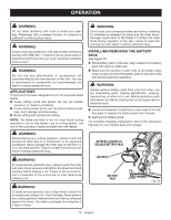
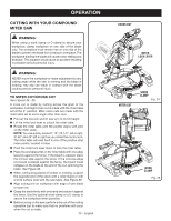
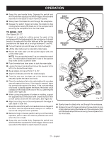
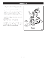
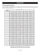
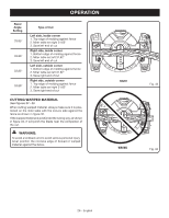
OPERATION TO COMPOUND MITER CUT See Figures 28 - 29. A compound miter cut is a cut made using a miter angle and a bevel angle at the same time. This type of cut is used to make picture frames, cut molding, and make boxes with sloping sides. To make this type of cut the control arm on the miter table must be rotated to the correct angle and the saw arm must be tilted to the correct bevel angle. Care should always be taken when making compound miter setups due to the interaction of the two angle settings. Adjustments of miter and bevel settings are interdependent with one another. Each time you adjust the miter setting you change the effect of the bevel setting. Also, each time you adjust the bevel setting you change the effect of the miter setting. It may take several settings to obtain the desired cut. The first angle setting should be checked after setting the second angle, since adjusting the second angle affects the first. Once the two correct settings for a particular cut have been obtained, always make a test cut in scrap material before making a finish cut in good material. Pull out the lock pin and lift saw arm to its full height. Lift the miter lock lever to unlock the miter table. Rotate the miter table until the pointer aligns with zero on the miter scale. NOTE: You can quickly locate 0°, 15°, 22-1/2°, left or right, 31.62° and 45° left or right as you rotate the control arm. The miter table will seat itself in one of the positive stop index points, located in base. Push the miter lock lever down to lock the miter table. Loosen the bevel lock knob and move the saw arm to the left to the desired bevel angle. Bevel angles can be set from 0° to 45°. Once the saw arm has been set at the desired angle, securely tighten the bevel lock knob. Recheck miter angle setting. Make a test cut in scrap material. Place the workpiece flat on the miter table with one edge securely against the fence. If the board is warped, place the convex side against the fence. If the concave edge of a board is placed against the fence, the board could collapse on the blade at the end of the cut, jamming the blade. When cutting long pieces of lumber or molding, support the opposite end of the stock with a roller stand or with a work surface level with the saw table. See Figure 30. Align the cutting line on the workpiece with the edge of saw blade or laser line. COMPOUND MITER CUT WORK CLAMP Fig. 28 45° X 45° COMPOUND MITER CUT Fig. 29 22 - English
-
 1
1 -
2
-
3
-
4
-
5
-
6
-
7
-
8
-
9
-
10
-
11
-
12
-
13
-
14
-
15
-
16
-
 17
17 -
 18
18 -
 19
19 -
 20
20 -
 21
21 -
 22
22 -
 23
23 -
 24
24 -
 25
25 -
 26
26 -
 27
27 -
28
-
29
-
30
-
31
-
32
-
33
-
34
-
35
-
36
-
37
-
38
-
39
-
40
-
41
-
42
-
43
-
44
-
45
-
46
-
47
-
48
-
49
-
50
-
51
-
52
-
53
-
54
-
55
-
56
-
57
-
58
-
59
-
60
-
61
-
62
-
63
-
64
-
65
-
66
-
67
-
68
-
69
-
70
-
71
-
72
-
73
-
74
-
75
-
76
-
77
-
78
-
79
-
80
-
81
-
82
-
83
-
84
-
85
-
86
-
87
-
88
 |
 |
