Ryobi P552 Manual 1 - Page 8
Know Your Compound Miter Saw
 |
View all Ryobi P552 manuals
Add to My Manuals
Save this manual to your list of manuals |
Page 8 highlights
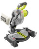
FEATURES KNOW YOUR COMPOUND MITER SAW See Figure 1. The safe use of this product requires an understanding of the information on the tool and in this operator's manual as well as a knowledge of the project you are attempting. Before use of this product, familiarize yourself with all operating features and safety rules. 7-1/4 in. BLADE A 7-1/4 in. blade is included with the compound miter saw. It will cut materials up to 1-1/2 in. thick or 4-1/4 in. wide, depending upon the angle at which the cut is being made. BEVEL LOCK KNOB The bevel lock knob securely locks your compound miter saw at desired bevel angles. Loosen the bevel lock knob to release the saw allowing the blade to be tilted for bevel cuts. Tighten the knob to lock the saw in place. Positive stop adjustment screws are located on each side of the saw arm. These adjustment screws are for making fine adjustments at 0° and 45°. BLADE WRENCH STORAGE See Figure 1. A blade wrench is packed with the saw. One end of the wrench is a phillips screwdriver and the other end is a hex key. Use the hex key end when installing or removing blade and the phillips end when removing or loosening screws. A storage area for the blade wrench is located in the saw's base. TO UNLOCK LOCK PIN TO LOCK MITER LOCK LEVER MITER FENCE REAR BRACKET/ CARRYING HANDLE LASER GUIDE LASER SWITCH MITER LOCK LEVER LASER GUIDE See Figure 2. When used properly, the laser guide makes accurate, precision cutting simple and easy. MITER FENCE The miter fence on the compound miter saw is used to secure your workpiece when making all cuts. MITER LOCK LEVER See Figure 2. The miter lock lever securely locks the saw at desired miter angles. To adjust miter table, rotate the miter lock lever forward to unlock the miter table. Rotate the lever toward the back of the saw to lock the miter table. POSITIVE STOPS ON MITER TABLE Positive stops have been provided at 0°, 15°, 22-1/2°, 31.62°, and 45°. The 15°, 22-1/2°, 31.62°, and 45° positive stops have been provided on both sides of the miter table. REAR BRACKET/CARRYING HANDLE See Figure 2. For convenience when carrying or transporting the miter saw, there is a carrying handle at the rear of the saw. To transport, turn off the saw and remove the battery pack, then lower the saw arm and lock it in the down position. Lock the saw arm by depressing the lock pin. "D" HANDLE SAW ARM LOCKED IN DOWN POSITION Fig. 2 8 - English
-
 1
1 -
2
-
 3
3 -
 4
4 -
 5
5 -
 6
6 -
 7
7 -
 8
8 -
 9
9 -
 10
10 -
 11
11 -
 12
12 -
 13
13 -
14
-
15
-
16
-
17
-
18
-
19
-
20
-
21
-
22
-
23
-
24
-
25
-
26
-
27
-
28
-
29
-
30
-
31
-
32
-
33
-
34
-
35
-
36
-
37
-
38
-
39
-
40
-
41
-
42
-
43
-
44
-
45
-
46
-
47
-
48
-
49
-
50
-
51
-
52
-
53
-
54
-
55
-
56
-
57
-
58
-
59
-
60
-
61
-
62
-
63
-
64
-
65
-
66
-
67
-
68
-
69
-
70
-
71
-
72
-
73
-
74
-
75
-
76
-
77
-
78
-
79
-
80
-
81
-
82
-
83
-
84
-
85
-
86
-
87
-
88
 |
 |
