Ryobi P552 Manual 1 - Page 15
Squaring The Blade To The Fence
 |
View all Ryobi P552 manuals
Add to My Manuals
Save this manual to your list of manuals |
Page 15 highlights
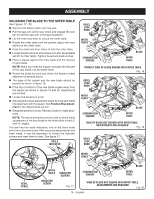
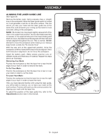
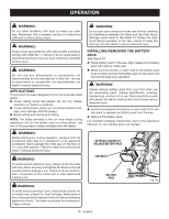
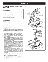
ASSEMBLY NOTE: Many of the illustrations in this manual show only portions of the compound miter saw. This is intentional so that we can clearly show points being made in the illustrations. Never operate the saw without all guards securely in place and in good operating condition. SQUARING THE BLADE TO THE FENCE See Figures 13 - 16. Remove the battery pack from the saw. Pull the saw arm all the way down and engage the lock pin to hold the saw arm in transport position. Unlock the miter lock lever. Rotate the miter table until the pointer aligns with zero dentent on the miter scale. Push the miter lock lever down to lock the miter table. Lay a square flat on the miter table. Place one leg of the square against the fence. Slide the other leg of the square against the flat part of saw blade. NOTE: Make sure that the square contacts the flat part of the saw blade, not the blade teeth. The edge of the square and the saw blade should be parallel as shown in figure 14. If the front or back edge of the saw blade angles away from the square as shown in figures 15-16, adjustments are needed. Using the blade wrench, loosen the socket head screws that secure the miter fence to the miter table. Rotate the miter fence left or right until the saw blade is parallel with the square. Retighten the screws securely and recheck the blade-tofence alignment. The saw has two scale indicators, one on the bevel scale and one on the miter scale. After squaring adjustments have been made, it may be necessary to loosen the indicator screws and reset them to zero. See figure 17. MITER FENCE BLADE MITER FRAMING TABLE SQUARE VIEW OF BLADE SQUARE WITH FENCE Fig. 14 MITER FENCE BLADE MITER FRAMING TABLE SQUARE VIEW OF BLADE NOT SQUARE WITH FENCE, ADJUSTMENTS ARE REQUIRED Fig. 15 SOCKET HEAD SCREW(S) SOCKET HEAD SCREW(S) MITER LOCK LEVER MITER FENCE 45 31.6 30 22.5 22.5 30 31.6 15 0 15 MITER FENCE 45 BLADE MITER FRAMING TABLE SQUARE Fig. 13 VIEW OF BLADE NOT SQUARE WITH FENCE, ADJUSTMENTS ARE REQUIRED Fig. 16 15 - English
-
 1
1 -
2
-
3
-
4
-
5
-
6
-
7
-
8
-
9
-
 10
10 -
 11
11 -
 12
12 -
 13
13 -
 14
14 -
 15
15 -
 16
16 -
 17
17 -
 18
18 -
 19
19 -
 20
20 -
21
-
22
-
23
-
24
-
25
-
26
-
27
-
28
-
29
-
30
-
31
-
32
-
33
-
34
-
35
-
36
-
37
-
38
-
39
-
40
-
41
-
42
-
43
-
44
-
45
-
46
-
47
-
48
-
49
-
50
-
51
-
52
-
53
-
54
-
55
-
56
-
57
-
58
-
59
-
60
-
61
-
62
-
63
-
64
-
65
-
66
-
67
-
68
-
69
-
70
-
71
-
72
-
73
-
74
-
75
-
76
-
77
-
78
-
79
-
80
-
81
-
82
-
83
-
84
-
85
-
86
-
87
-
88
 |
 |
