Ryobi WS720 Operation Manual - Page 8
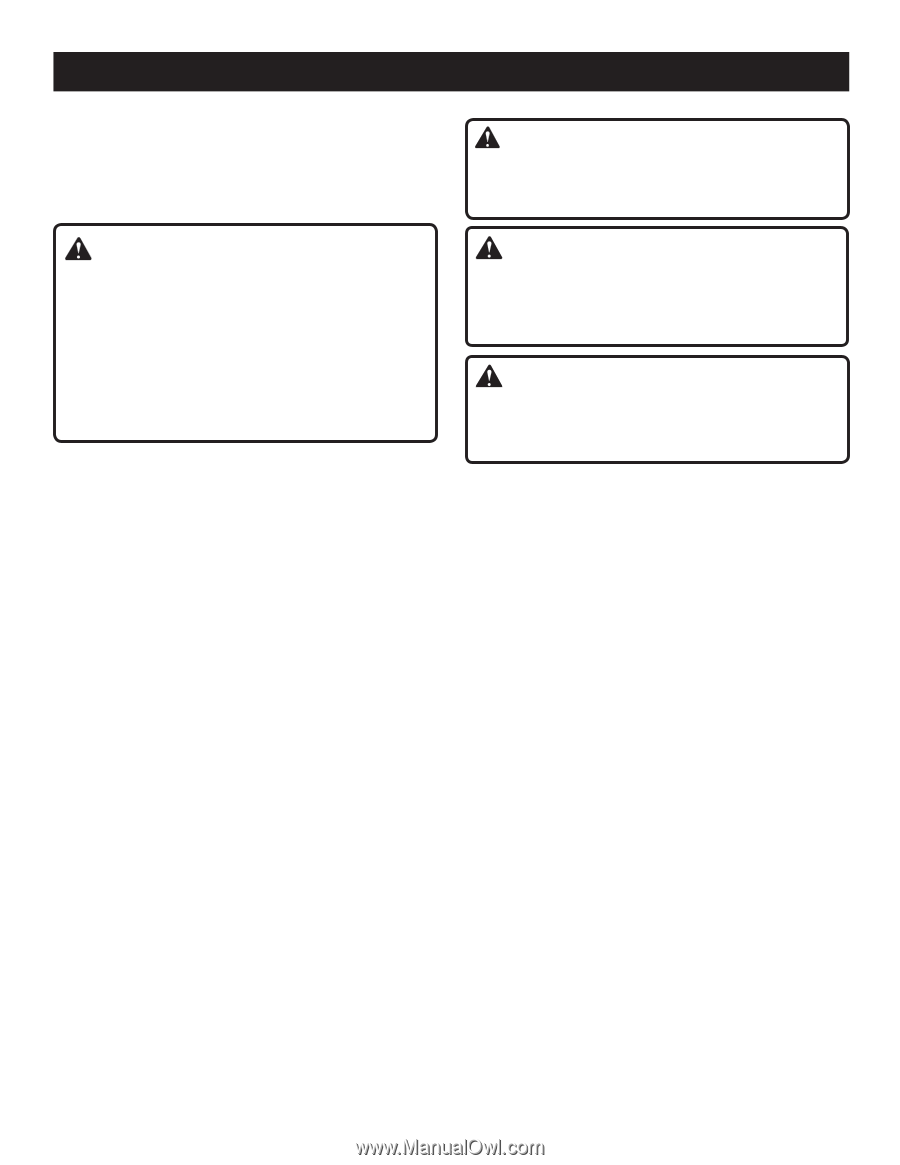
Assembly - 7 tile saw
 |
View all Ryobi WS720 manuals
Add to My Manuals
Save this manual to your list of manuals |
Page 8 highlights
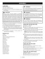
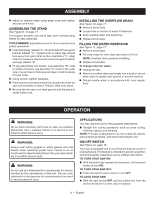
ASSEMBLY UNPACKING See Figure 4, page 16. This product requires assembly. Carefully lift the saw from the carton and place on a level work surface. Warning: If any parts are damaged or missing do not operate this tool until the parts are replaced. Failure to heed this warning could result in serious personal injury. WARNING: This new product has been shipped in a partially assembled condition as described below. Carefully check the packing list below to ensure all items are included in the package. The packing list describes all loose items that are not assembled to the product as shipped. Do not operate the product if any packing list items are already assembled to your product when you unpack it. Call the customer service number below for assistance. Operation of a product that may have been improperly preassembled could result in serious personal injury. Inspect the tool carefully to make sure no breakage or damage occurred during shipping. Do not discard the packing material until you have carefully inspected and satisfactorily operated the tool. The saw is factory set for accurate cutting. After assembling it, check for accuracy. If shipping has influenced the settings, refer to specific procedures explained in this manual. If any parts are damaged or missing, please call 1-800-525-2579 for assistance. PACKING LIST Tile saw Bevel table Splash hood with knob and hex bolt Splash hood bracket Screws (2) Overflow drain Rip guide Miter guide Hex wrench Arbor wrench Support bracket "A" Support bracket "B" Stand legs "A" (2) Stand legs "B" (2) Leg stand brace (2) Leg stand nut (2) Leg stand bolt (2) Operator's Manual warning: Do not attempt to modify this tool or create accessories not recommended for use with this tool. Any such alteration or modification is misuse and could result in a hazardous condition leading to possible serious personal injury. WARNING: Do not connect to power supply until assembly is complete. Failure to comply could result in accidental starting and possible serious personal injury. Installing the splash hood See Figure 5 - 6, page 16. Remove bevel table. Install the L-shaped splash hood bracket into the lip located under the table behind the wheel. Install the washers and screws into table and through splash hood bracket then tighten securely. NOTE: Be sure that hood bracket is aligned with cutting wheel so that it does not interfere with material being cut. Align splash hood with wheel and slide over bracket. Line up through holes in splash hood with slot in splash hood bracket. NOTE: Always adjust splash hood horizontally to table and slightly above tile thickness. Hood should not be touching tile. Install hex bolt through hood and bracket. Thread knob onto bolt and tighten to desired height. Replace bevel table. Installing the rip guide See Figure 7, page 17. Turn knob on rip guide counterclockwise to loosen. Slide rip guide onto side of table. Use rip guide scale, located on front and rear of table, to set rip guide to desired width of cut. Turn rip guide knob clockwise to tighten securely. Installing the miter guide See Figure 7, page 17. Adjust rip guide to desired position and secure. Slide miter guide onto rip guide from front. 8 - English
-
 1
1 -
2
-
 3
3 -
 4
4 -
 5
5 -
 6
6 -
 7
7 -
 8
8 -
 9
9 -
 10
10 -
 11
11 -
 12
12 -
 13
13 -
14
-
15
-
16
-
17
-
18
-
19
-
20
-
21
-
22
-
23
-
24
-
25
-
26
-
27
-
28
-
29
-
30
-
31
-
32
-
33
-
34
-
35
-
36
-
37
-
38
-
39
-
40
-
41
-
42
-
43
-
44
 |
 |