Samsung PPM42M5H User Manual (ENGLISH) - Page 7
Rear Panel, Ext Speaker 8, Pc1 In/out, Audio, Pc2 Bnc In, Rs-232c, Dvi In, Component - monitor
 |
UPC - 729507800479
View all Samsung PPM42M5H manuals
Add to My Manuals
Save this manual to your list of manuals |
Page 7 highlights
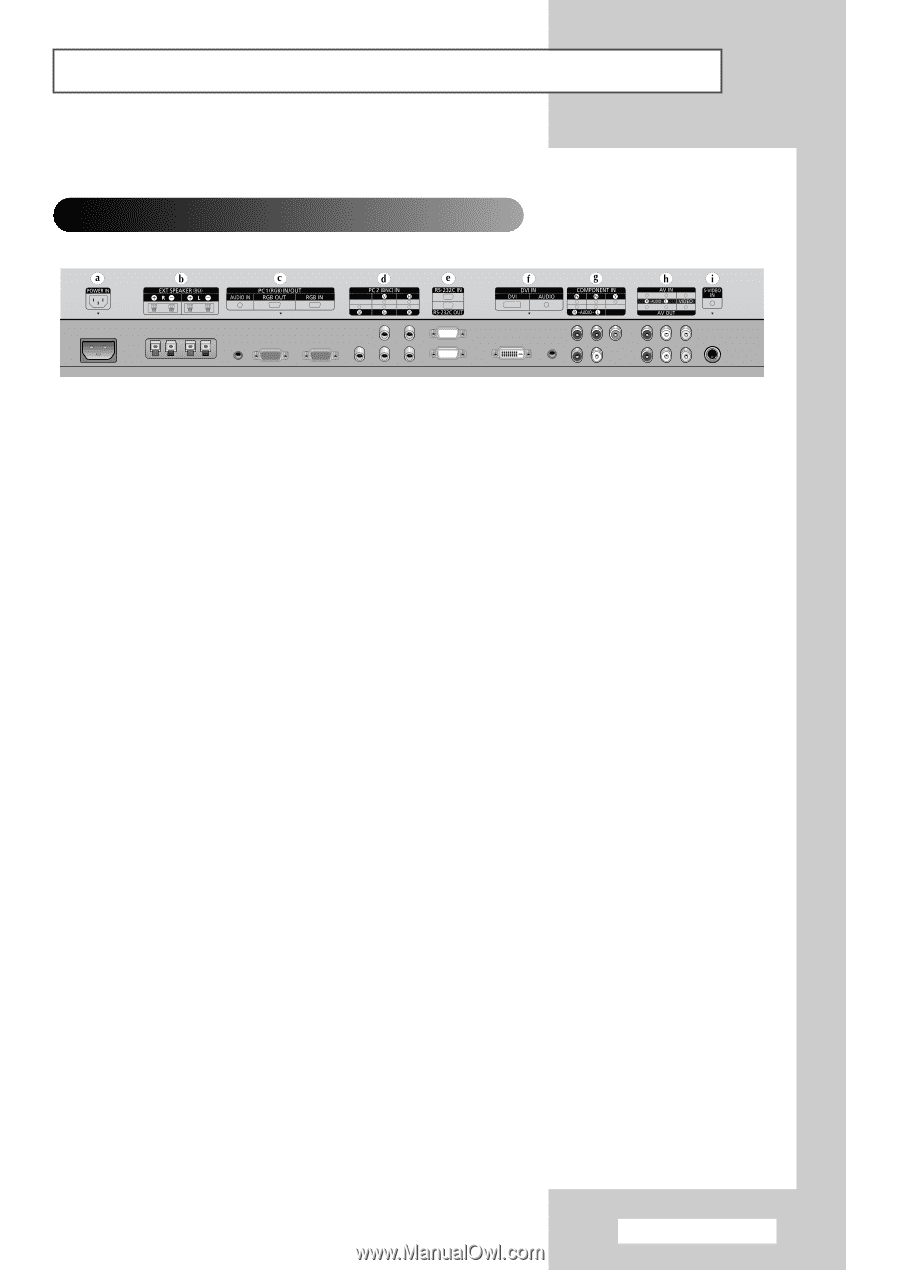
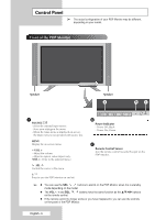
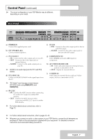
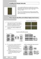
Control Panel (continued) ➢ The actual configuration of your PDP Monitor may be different, depending on your model. Rear Panel a) POWER IN Connect the supplied power cord. b) EXT SPEAKER (8Ω) Connect external speakers. c) PC1 IN/OUT - IN : Connect to the video output jack on your PC. - OUT : Connect to the video input jack on external devices. - AUDIO : Connect to the audio output jack on your PC. ➢ AUDIO is an audio input jack for PC1 and PC2 modes. d) PC2 (BNC) IN Connect for RGB(Y/PB/PR)HV video signal input from the PC. ➢ "PC Mode" from this page onward means PC1/PC2 mode using RGB1(PC1) and RGB2(PC2). e) RS-232C - IN : Used for the MDC function when connecting PC or RS-232C output of another PDP Monitor. - OUT : Used for the MDC function when connecting with RS-232C input of another PDP Monitor. ➢ For further details about connections, refer to Page 12. f) DVI IN - DVI : Connect to the video output jack for device with DVI output. - AUDIO : Connect to the audio output jack for devices with DVI output. g) COMPONENT IN Video (Y/PB/PR) and audio (L/R) inputs for component. h) AV (VIDEO/AUDIO L/R) - IN : Video and audio inputs for external devices, such as a camcorder or VCR. - OUT : Outputs for external devices. i) S-VIDEO IN Video input for external devices with an S-Video output, such as a camcorder or VCR. ➢ For further details about connection, refer to pages 43~46. ➢ Whenever you connect an audio or video system to your PDP Monitor, ensure that all elements are switched off. Refer to the documentation supplied with your equipment for detailed connection instructions and associated safety precautions. English - 7
-
 1
1 -
 2
2 -
 3
3 -
 4
4 -
 5
5 -
 6
6 -
 7
7 -
 8
8 -
 9
9 -
 10
10 -
 11
11 -
 12
12 -
13
-
14
-
15
-
16
-
17
-
18
-
19
-
20
-
21
-
22
-
23
-
24
-
25
-
26
-
27
-
28
-
29
-
30
-
31
-
32
-
33
-
34
-
35
-
36
-
37
-
38
-
39
-
40
-
41
-
42
-
43
-
44
-
45
-
46
-
47
-
48
-
49
-
50
-
51
-
52
-
53
-
54
-
55
-
56
-
57
-
58
 |
 |