Samsung WF350ANP/XAA Trouble Shooting Guide (user Manual) (ver.1.0) (English) - Page 20
Problem Checking And Method Of Pcb, Warning
 |
View all Samsung WF350ANP/XAA manuals
Add to My Manuals
Save this manual to your list of manuals |
Page 20 highlights
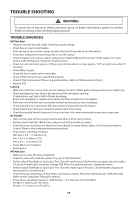
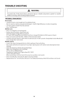
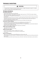
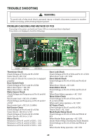
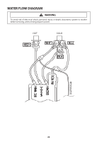
TROUBLE SHOOTING WARNING To avoid risk of electrical shock, personal injury or death; disconnect power to washer before servicing, unless testing requires power. PROBLEM CHECKING AND METHOD OF PCB - If you plug in the power cord and turn Power S/W on, memorized data is displayed. If any data is not displayed, check the followings. Thermistor Check Check Voltage at Pin #4 and #5 of CN7 Tester Check = DC 2.5V If it reads 5V, Check if its connector is engaged properly Door Switch Check Check Voltage at Pin #1 and #3 of CN4 When Door Open = DC 25V When Door Close = DC 0V Water Sensor Check Check Voltage and Frequency at Pin #5 and #6 of CN7 Reset water level = DC2.5V, 25.8KHz Check Voltage and Frequency at Pin #5 and #7 of CN7 Reset water level = DC2.5V, 25.8KHz Hall Sensor Check Check Voltage at Pin #4 and #2 of CN6 Tester Check = DC 0V or 3.75V Check Voltage at Pin #4 and #3 of CN6 Tester Check = DC 0V or 3.75V Motor Check Resistance at Pin #1 and #2 of CN5 = 12Ω Resistance at Pin #1 and #3 of CN5 = 12Ω Resistance at Pin #2 and #3 of CN5 = 12Ω Door Lock Check Check Voltage at Pin #3 of CN2 and Pin #1 of CN3 When Door Lock = AC 120V Door Unlock Check Check Voltage at Pin #3 of CN2 and Pin #2 of CN3 When Door Unlock = AC 120V Drain Motor Check Check Voltage at Pin #3 of CN2 and Pin #3 of CN3 When Drain Motor operates = AC 120V Water Valve Check Check Voltage at Pin #3 of CN2 and Pin #1,2,7,8,9 of CN3 When each valve operates = AC 120V AC Power Check Check Voltage at Pin #1 and #2 of CN2 Tester Check = AC 120V Wash Heater Relay Check Check Voltage at Pin #3 of CN2 and PIN #2 of RY3 When Heater Relay operates = AC 120V Steam Heater Relay Check(Only Steam Models) Check Voltage at Pin #3 of CN2 and PIN #2 of RY4 When Heater Relay operates = AC 120V 20
-
 1
1 -
2
-
3
-
4
-
5
-
6
-
7
-
8
-
9
-
10
-
11
-
12
-
13
-
14
-
 15
15 -
 16
16 -
 17
17 -
 18
18 -
 19
19 -
 20
20 -
 21
21 -
 22
22 -
 23
23 -
 24
24
 |
 |