Sanyo VCC-XZ600N Installation Manual - Page 6
Checking the menus and zoom position using simple, monitor output
 |
View all Sanyo VCC-XZ600N manuals
Add to My Manuals
Save this manual to your list of manuals |
Page 6 highlights
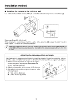
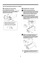
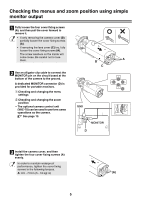
Checking the menus and zoom position using simple monitor output 1 Fully loosen the four cover fixing screws (A), and then pull the cover forward to remove it. • If only removing the camera cover (B), partially loosen the cover fixing screws (A). • If removing the lens cover (C) too, fully loosen the cover fixing screws (A). The screw washers on the inside will come loose. Be careful not to lose them. A B C 2 Use an alligator clip cable to connect the MONITOR pin on the circuit board at the bottom of the camera to the ground. A dedicated MONITOR connector (D) is provided for portable monitors. 1Checking and changing the menu settings 2Checking and changing the zoom position • The optional camera control unit (VAC-70) can be used to perform same operations as the camera. & See page 13. GND MONITOR D 3 Install the camera cover, and then tighten the four cover fixing screws (A) evenly. In order to maintain waterproof performance, tighten the cover fixing screws to the following torques. A: 0.5 - 7 N·m (5 - 10 kgf·m) (A) 5
-
 1
1 -
 2
2 -
 3
3 -
 4
4 -
 5
5 -
 6
6 -
 7
7 -
 8
8 -
 9
9 -
 10
10 -
 11
11 -
 12
12 -
13
-
14
-
15
-
16
-
17
-
18
-
19
-
20
-
21
-
22
-
23
-
24
-
25
-
26
-
27
-
28
-
29
-
30
-
31
-
32
-
33
-
34
-
35
-
36
-
37
-
38
-
39
-
40
-
41
-
42
-
43
-
44
-
45
-
46
-
47
-
48
-
49
-
50
-
51
-
52
-
53
-
54
-
55
-
56
-
57
-
58
-
59
-
60
-
61
-
62
-
63
-
64
 |
 |
