Sanyo VCC-ZM600N Installation Manual
Sanyo VCC-ZM600N - Network Camera Manual
 |
View all Sanyo VCC-ZM600N manuals
Add to My Manuals
Save this manual to your list of manuals |
Sanyo VCC-ZM600N manual content summary:
- Sanyo VCC-ZM600N | Installation Manual - Page 1
CCD Camera THIS INSTALLATION SHOULD BE MADE BY A QUALIFIED SERVICE PERSON AND SHOULD CONFORM TO ALL LOCAL CODES. VCC-ZM600P Deutsch Français English Please read this installation manual carefully in order to ensure correct installation. In addition, be sure to read carefully the electronic - Sanyo VCC-ZM600N | Installation Manual - Page 2
problem Do not use the unit if smoke or a strange odor comes from the unit, or if it seems not to function correctly. Turn off the power immediately and disconnect the power cord, and then consult your dealer or an Authorized Sanyo Service sure to read all accompanying instructions. Make sure that no - Sanyo VCC-ZM600N | Installation Manual - Page 3
by official certification company which is authorized by Russian Federation. This installation manual and the electronic manual are copyrighted by SANYO Electric Co., Ltd. No materials contained in these manuals may be reproduced in any format without the prior permission of the copyright - Sanyo VCC-ZM600N | Installation Manual - Page 4
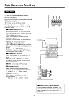
detects intruders. Connect this terminal to an external alarm switch or an infrared sensor, etc. Used to switch the viewing mode manually between the color mode and the black/white mode. To do so, select [DAY/NIGHT], choose "COLOR", and set the [EXT ALARM] to the - Sanyo VCC-ZM600N | Installation Manual - Page 5
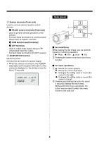
3 System terminals (Push-lock) Used to connect external system control devices. 1 RS-485 control terminals (Push-lock) Used to perform remote operations of the camera. Connect these terminals to a communication device such as system controller. 2 COM terminal (earth terminal) 3 UTP terminals Used to - Sanyo VCC-ZM600N | Installation Manual - Page 6
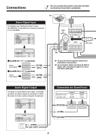
until all other connections have been completed. ✱1 Alarm Signal Input For details, see "Setting the Alarm Input (ALARM IN)" in the electronic manual contained in the CD-ROM. SYNC CAMERA LENS ALARM PRIVACY MASK PASSWORD LANGUAGE OPTION INT 1 y SET y SET y SET y SET y SET y SET y POWER - Sanyo VCC-ZM600N | Installation Manual - Page 7
Connection with a communication device for remote operation Controller ✱3 UTP (Unshield Twist Pair) cable: LAN Category 5 or higher ✱3 NVT Digital Video Recorder etc. Receiver SYSTEM DEVICE (ex. Monitor) To output video signal, select the connection of a coaxial cable or a UTP cable. Power - Sanyo VCC-ZM600N | Installation Manual - Page 8
camera can be controlled remotely by establishing the RS-485 or coaxial super imposed communication. & [OPTION] ⇒ [SYSTEM] b You can switch the viewing mode manually between the color mode and the black/white mode. & [CAMERA] ⇒ [COLOR] ⇒ [EXT ALARM] Camera Title You can set and display the camera - Sanyo VCC-ZM600N | Installation Manual - Page 9
Day/Night Function According to the luminance level, the viewing mode will be switched automatically between the color mode and the black/white mode. You can adjust the luminance threshold for switching the viewing mode. LOW MID HIGH B/W Color Switchover point & [CAMERA] ⇒ [DAY/NIGHT] ⇒ [AUTO] - Sanyo VCC-ZM600N | Installation Manual - Page 10
on the camera. The optional camera control unit (VAC-70) can be used to perform same operations as the camera. For details, refer to the instruction manual for the camera control unit. 1 Displays the main menu. Press and hold down the SET button for 3 seconds or longer to display the main menu - Sanyo VCC-ZM600N | Installation Manual - Page 11
Learning the Menu Setting Operations 1 Display the main menu. SET Press and hold the button for about 3 seconds. SYNC CAMERA LENS ALARM PRIVACY MASK PASSWORD LANGUAGE OPTION INT 1 y SET y SET y SET y SET y SET y SET y PRESET MENU OFF END 2 Select a menu item. Menu item - Sanyo VCC-ZM600N | Installation Manual - Page 12
Learning the Menu Setting Operations 5 Return to the previous screen. Select [MENU] - "BACK" at the bottom of the screen, and press the SET button. IRIS WHITE BALANCE BLC SHUTTER APERTURE AGC GAMMA MOTION POSITION DAY/NIGHT PRESET MENU AUTO y ATW y OFF OFF ON y ON y 0.45 OFF OFF AUTO y OFF BACK - Sanyo VCC-ZM600N | Installation Manual - Page 13
as troubleshooting. Requirements for viewing the electronic manual Guide to the Setting Menu" on the menu located on the left of the screen. • Viewing definitions of glossary Click "Glossary" on the menu located on the left of the screen. • Viewing troubleshooting procedure Click "Troubleshooting - Sanyo VCC-ZM600N | Installation Manual - Page 14
collector Control voltage: ± (6 - 12) V DC System connection terminals (RS-485/Coaxial, UTP (NVT built-in), support of camera control unit (VAC-70)) -10 - +50°C/14 - 122°F, 90% RH max. (no condensation) product names in this manual are the registered trademarks or trademarks of their respective owners - Sanyo VCC-ZM600N | Installation Manual - Page 15
MANUEL D'INSTALLATION Caméra CCD couleurs CETTE INSTALLATION DOIT ETRE EFFECTUEE PAR UNE PERSONNE QUALIFIEE DU SERVICE TECHNIQUE ET DOIT ETRE CONFORME A TOUS LES CODES LOCAUX. VCC-ZM600P Deutsch Français English Veuillez lire ce manuel d'installation très attentivement afin d'effectuer une - Sanyo VCC-ZM600N | Installation Manual - Page 16
d'alimentation, puis adressez-vous à votre revendeur ou à un Centre de service Sanyo autorisé. ■ Ne l'ouvrez pas et ne le modifiez pas N'ouvrez pas utiliser un chiffon traité chimiquement, assurez-vous de lire toutes les instructions qui l'accompagnent. Assurez-vous qu'aucune pièce en plastique ou - Sanyo VCC-ZM600N | Installation Manual - Page 17
cho, Daito City, Osaka 574-8534, Japan Le manuel d'installation et le manuel électronique sont protégés par les droits d'auteur de SANYO Electric Co., Ltd. Aucun des éléments contenus dans ces manuels ne peut être reproduit, sous quelque format que ce soit, sans l'autorisation préalable du dé - Sanyo VCC-ZM600N | Installation Manual - Page 18
Dénomination et fonctions des pièces Panneau arrière 1 Connecteur VIDEO OUT (type BNC) Émet signal vidéo. Connectez cette connecteur à la borne d'entrée vidéo de l'appareil externe. 2 Bornes de commande à poussoir Pour les fonctions de commande comme la commande à distance de la caméra ou la entr - Sanyo VCC-ZM600N | Installation Manual - Page 19
3 Bornes de système (Verrouillage à poussoir) Sert à connecter des appareils externes de contrôle système. 1 Bornes de commande RS-485 à poussoir Utilisé pour le fonctionnement à distance de la caméra. Reliez ces bornes à un appareil de communication (contrôleur de système par ex.). 2 Borne COM ( - Sanyo VCC-ZM600N | Installation Manual - Page 20
Branchements Ne branchez pas le cordon d'alimentation tant que les autres branchements n'ont pas ete effectues. ✱1 Entrée du signal d'alarme Pour tout détail, consultez « Réglage de l'entrée d'alarme (ENT ALARME) » dans le manuel électronique contenu dans le CD-ROM. SYNC CAMERA LENTILLE ALARME - Sanyo VCC-ZM600N | Installation Manual - Page 21
Connexion avec un appareil de communication pour la commande à distance Contrôleur ✱3 Câble UTP (Unshield Twist Pair - paire torsadée non blindée): LAN de catégorie 5 ou supérieure ✱3 NVT Enregistreur vidéo numérique, etc. Récepteur SYSTEM DEVICES (ex. Moniteur) Pour émettre un signal vidéo, sé - Sanyo VCC-ZM600N | Installation Manual - Page 22
Caractéristiques & Vous pouvez effectuer les différents réglages sur la caméra en naviguant à travers les écrans de menu. Fonction zoom b Vous pouvez mémoriser les réglages de zoom et de mise au point des positions de surveillance via le numéro de configuration caméra. & [CAMERA] ⇒ [POSITION] - Sanyo VCC-ZM600N | Installation Manual - Page 23
Fonction Jour/Nuit Selon le niveau de luminance, le mode de visualisation commute automatiquement entre le mode couleur et le mode noir et blanc. Vous pouvez régler le seuil de luminance déterminant la commutation du mode de visualisation. BAS MOYEN ELEVE N/B Couleur Point de commutation & [ - Sanyo VCC-ZM600N | Installation Manual - Page 24
éra. La télécommande en option (VAC-70) peut effectuer les mêmes opérations que la caméra. Pour plus de détails, consultez le manuel d'instructions de la télécommande en question. 1 Affiche le menu principal. Pressez et maintenez enfoncé le bouton SET pendant 3 secondes ou plus pour afficher le menu - Sanyo VCC-ZM600N | Installation Manual - Page 25
Apprentissage des opérations de réglage menu 1 Affichez le menu principal. SET Appuyez et maintenez enfoncé le bouton pendant environ 3 secondes. SYNC CAMERA LENTILLE ALARME MASQUE M/PASSE LANGUE OPTION INT 1 y REG y REG y REG y REG y REG y REG y PREREGLAGE MENU ARR - Sanyo VCC-ZM600N | Installation Manual - Page 26
Apprentissage des opérations de réglage menu 5 Retournez à l'écran précédent. Sélectionnez [MENU] - « RETOUR » au bas de l'écran, puis pressez le bouton SET. IRIS EQUIL BLANC BLC OBTURATEUR OUVERTURE CAG GAMMA MOUVEMENT POSITION JOUR/NUIT PREREGLAGE MENU AUTO y ATW y ARR ARR MAR y MAR y 0.45 ARR - Sanyo VCC-ZM600N | Installation Manual - Page 27
des procédures de définition menu pour chaque utilisation Cliquez sur « Guide au menu de réglage » sur le menu situé à gauche de gauche de l'écran. & Vous pouvez également consulter « How to use this manual (Comment utiliser ce manuel) » pour mieux comprendre la structure du manuel électronique - Sanyo VCC-ZM600N | Installation Manual - Page 28
Mode de communication Humidité/température ambiantes de service Source d'alimentation Consommation d'énergie Dimensions (La de ± (6 à 12) V DC Bornes de connexion système (RS-485/Coaxial, UTP (NVT intégré), support télécommande caméra (VAC-70)) -10 - +50°C, 90% RH maxi (pas de condensation) 24 V AC - Sanyo VCC-ZM600N | Installation Manual - Page 29
INSTALLATIONSANLEITUNG CCD-Farbkamera DIESE INSTALLATION IST QUALIFIZIERTEM SERVICE-PERSONAL VORBEHALTEN UND MUSS MIT ALLEN LOKALEN GESETZESVORSCHRIFTEN KONFORM SEIN. VCC-ZM600P Deutsch Français English Lesen Sie bitte diese Anleitung sorgfältig durch, um die einwandfreie Installation - Sanyo VCC-ZM600N | Installation Manual - Page 30
. Schalten Sie das Gerät sofort aus, ziehen Sie das Netzkabel aus der Steckdose und wenden Sie sich an Ihren Händler oder an ein autorisiertes Sanyo-Kundendienstzentrum. ■ Das Gerät darf nicht geöffnet und es dürfen keine Änderungen vorgenommen werden Das Gehäuse darf nicht geöffnet werden, weil es - Sanyo VCC-ZM600N | Installation Manual - Page 31
nur für EU-Länder und finden in den anderen Ländern der Welt keine Anwendung. SANYO FISHER Sales (Europe) GmbH Stahlgruberring 4, D-81829 München, Germany SANYO Electric Co., Ltd. 1-1, Sanyo-cho, Daito City, Osaka 574-8534, Japan Die Installationsanleitung und die elektronische Anleitung unterliegen - Sanyo VCC-ZM600N | Installation Manual - Page 32
Bezeichnung und Funktionen der Teile Rückseite 1 Video-Ausgangsanschluss (VIDEO OUT: BNC-Buchse) Für die Ausgabe des Videosignals. Verbinden Sie diese Anschluss mit der Videoeingangsbuchse (VIDEO IN) des externen Geräts. 2 Steuerklemmen (mit Sicherung) Für die Steuerfunktionen wie beispielsweise - Sanyo VCC-ZM600N | Installation Manual - Page 33
3 Systemklemmen (mit Sicherung) Für den Anschluss von externen Systemsteuergeräten. 1 RS-485 Steuerklemmen (mit Sicherung) Für die Fernbedienung der Kamera. Schließen Sie diese Klemmen an ein Kommunikationsgerät wie beispielsweise ein Systemsteuergerät an. 2 COM-Klemme (Erdungsklemme) 3 UTP-Buchsen - Sanyo VCC-ZM600N | Installation Manual - Page 34
Anschlüsse Das Netzkabel nicht anschließen, bevor nicht alle anderen Anschlüsse ausgeführt wurden. ✱1 Alarmeingangsignal Weitere Einzelheiten finden Sie unter „Einstellen des Alarmeingangs (ALARM EIN)" in der elektronischen Anleitung auf der CD-ROM. SYNC KAMERA OBJEKTIV ALARM PRIV.MASK. KENNWORT - Sanyo VCC-ZM600N | Installation Manual - Page 35
Anschluss an ein Kommunikationsgerät zur Fernbedienung Controller ✱3 UTP-Kabel (Unshield Twist Pair = Nicht abgeschirmtes verdrilltes Leiterpaar): LAN Kategorie 5 oder höher ✱3 NVT Digital-Videorecorder etc. Empfänger SYSTEM DEVICES (z.B. Monitor) Schließen Sie für die Ausgabe des Videosignals - Sanyo VCC-ZM600N | Installation Manual - Page 36
Merkmale & Sie können die Einstellungen der Kamera über die Navigation durch die Menübildschirme vornehmen. Zoomfunktion b Sie können die Zoom- und Scharfeinstellungswerte von Überwachungsorten nach Kameraeinstellnummer speichern. & [KAMERA] ⇒ [POSITION] KAMERA 1 KAMERA 2 POSITION POSITION - Sanyo VCC-ZM600N | Installation Manual - Page 37
Tag/Nacht-Funktion Der Anzeigemodus wird entsprechend dem Helligkeitspegel automatisch vom Farbe-Modus auf den Schwarz/Weiß-Modus umgeschaltet. Sie können den Schwellenwert für die Helligkeit einstellen, bei dem der Anzeigemodus umgeschaltet wird. NIEDRIG MITTE HOCH S/W Farbe Umschaltpunkt & [ - Sanyo VCC-ZM600N | Installation Manual - Page 38
Vornehmen der Einstellungen in den Menübildschirmen Diese Anleitung und die elektronische Anleitung auf der mitgelieferten CD-ROM umfassen die Beschreibung der mit den Tasten an der Kamera verfügbaren Funktionen. Mit dem optional erhältlichen VAC-70 Kamerasteuergerät können Sie die gleichen - Sanyo VCC-ZM600N | Installation Manual - Page 39
Erlernen der Menüeinstellfunktionen 1 Erlernen der Menüeinstellfunktionen SET Drücken Sie die Taste und halten Sie sie circa 3 Sekunden lang gedrückt. SYNC KAMERA OBJEKTIV ALARM PRIV.MASK. KENNWORT SPRACHE OPTION VOREINST. MENUE INT 1 y EINSTy EINSTy EINSTy EINSTy EINSTy - Sanyo VCC-ZM600N | Installation Manual - Page 40
Erlernen der Menüeinstellfunktionen 5 Kehren Sie zum vorherigen Bildschirm zurück. Wählen Sie [MENUE] - „ZURUECK" unten im Bildschirm und drücken Sie die SET-Taste. IRIS WEISSABGLEICH GEGENL.KOMP. VERSCHLUSS BLENDE AGC GAMMA BEWEGUNGSENSOR POSITION TAG/NACHT VOREINST. MENUE AUTO y ATW y AUS AUS - Sanyo VCC-ZM600N | Installation Manual - Page 41
aus (Bildschirm 1). 3 Wählen Sie die gewünschte Sprache aus (Bildschirm 2). Das elektronische Handbuch wird geöffnet. 4 Klicken Sie auf „Open this manual" (Anleitung öffnen). Klicken Sie im Menü links im Bildschirm einen Menüpunkt an, zu dem Sie die relevanten Informationen erhalten möchten. Die - Sanyo VCC-ZM600N | Installation Manual - Page 42
Wichtigste technische Daten Fernsehsystem Bildsensor Effektive Bildpunkte Abtastsystem Synchronisierung Videoausgang Horizontale Auflösung Mindestbeleuchtung Signal-Rausch-Verhältnis Videoausgang Objektiv Elektronischer Zoom Alarmeingang Alarmausgang Steuerung von Scharfeinstellung/Zoom - Sanyo VCC-ZM600N | Installation Manual - Page 43
安装手册 摄像头 VCC-ZM600P CD-ROM 目录 1 3 5 7 9 10 CD-ROM 12 13 Dimensions Deutsch Français English A 镜头盖 (B) (A) 置。 ✱ (B) (A) - Sanyo VCC-ZM600N | Installation Manual - Page 44
用户须知 注意事项 SANYO Electric Co., Ltd 1 - Sanyo VCC-ZM600N | Installation Manual - Page 45
2 - Sanyo VCC-ZM600N | Installation Manual - Page 46
后面板 1 VIDEO OUT BNC型) 2 1 ALARM IN 1/2端子 Day/Night 2 ALARM OUT端子 3 COM 4 FOCUS端子 DC ± (6 - 12 V 5 ZOOM端子 DC ± (6 - 12 V 123 A B COM RS485 UTP 3 POWER指示灯 1 2 ALARM IN 1 ALARM OUT FOCUS POWER VIDEO OUT A B COM RS485 UTP ALARM IN 2 AC24V GND DC12V 4 COM - Sanyo VCC-ZM600N | Installation Manual - Page 47
3 1 RS-485 2 COM 3 UTP端子 通过使用UTP NVT接收器。 4 AC24V/DC12V端子 POWER 10 秒钟。 CAMERA VER PROTOCOL ADDRESS X.XX-XX XXXX X 侧面板 1 2 SET b 1 c: 广角 d: 望远 j: 近 l: 远 2 b 1 j l c d 2 3 4 - Sanyo VCC-ZM600N | Installation Manual - Page 48
连接 ✱1 CD-ROM ALARM IN)"一 节。 SYNC CAMERA LENS ALARM PRIVACY MASK PASSWORD LANGUAGE OPTION INT 1 y SET y SET y SET y SET y SET y SET y ALARM IN 1 POWER VIDEO OUT A B COM RS485 UTP ALARM IN 2 AC24V GND BNC类型 COM ZOOM ALARM OUT FOCUS ALARM ALARM IN ALARM OUT ALARM - Sanyo VCC-ZM600N | Installation Manual - Page 49
控制器 ✱3 UTP (Unshield Twist Pair LAN Category 5 以上 ✱3 NVT 接收器 SYSTEM DEVICES UTP b 使用AC 24 V GND ~ ~ 请使用比18 AWG b 使用DC 12 V - + 请使用比18 AWG RG-59U RG-59U (3C-2V) RG-6U (5C-2V) RG-11U (7C-2V) 长度 最长250m 最长500m 最长600m (COM) (ALARM IN 1ড2) SYNC - Sanyo VCC-ZM600N | Installation Manual - Page 50
功能 变焦功能 b & [CAMERA] ⇒ [POSITION] CAMERA 1 CAMERA 2 POSITION POSITION x 1.0 SET y x 3.0 SET y b & [LENS] ⇒ [ZOOM] ⇒ [EL ZOOM] b & [LENS] ⇒ [ZOOM] ⇒ [SPEED] 遥控操作 b RS-485 & [OPTION] ⇒ [SYSTEM] b & [CAMERA] ⇒ [COLOR] ⇒ [EXT ALARM] b 16个字符) & [OPTION] ⇒ [DISPLAY] ⇒ [ - Sanyo VCC-ZM600N | Installation Manual - Page 51
Day/Night 功能 LOW MID HIGH फռ ث & [CAMERA] ⇒ [DAY/NIGHT] ⇒ [AUTO] ⇒ [LEVEL] & [CAMERA] ⇒ [WHITE BALANCE] ⇒ [ATW] ⇒ [MASKING] 背光补偿 b 48 5 & [CAMERA] ⇒ [BLC] ⇒ [MULT] or [CENT] b & [CAMERA] ⇒ [BLC] ⇒ [MASK] 隐私掩蔽 4 & [PRIVACY MASK] & [CAMERA] ⇒ [SHUTTER] 8 - Sanyo VCC-ZM600N | Installation Manual - Page 52
CD-ROM VAC-70 1 SET按钮3 2 3 4 j: 近 l: 远 d: 广角 c: 望远 A 2 4 1 SET 3 B 使用VAC-70 2 4 1 3 9 - Sanyo VCC-ZM600N | Installation Manual - Page 53
1 SET 3秒钟。 SYNC CAMERA LENS ALARM PRIVACY MASK PASSWORD LANGUAGE OPTION INT 1 y SET y SET y SET y SET y SET y SET y PRESET MENU OFF END 2 菜单项 光标 SYNC CAMERA LENS ALARM PRIVACY MASK PASSWORD LANGUAGE OPTION PRESET MENU INT 1 y SET y SET y SET y SET y SET - Sanyo VCC-ZM600N | Installation Manual - Page 54
5 MENU] - "BACK SET 按钮。 IRIS WHITE BALANCE BLC SHUTTER APERTURE AGC GAMMA MOTION POSITION DAY/NIGHT PRESET MENU AUTO y ATW y OFF OFF ON y ON y 0.45 OFF OFF AUTO y OFF BACK 6 MENU] - "BACK dc END SET 按钮。 PRESET MENU OFF BACK SET PRESET MENU OFF END SET PRESET MENU - Sanyo VCC-ZM600N | Installation Manual - Page 55
CD-ROM光盘) CD-ROM 浏览器:Internet Explorer 6.0 JavaScript和Cookie ActiveX控件。 1 将CD-ROM CD 2 1)。 (屏幕1) 3 2 4 单击 "Open this manual "图标。 (屏幕2) How to use this manual 安装手册 Adobe Reader Adobe Reader Adobe 网站 http://www.adobe.com 12 - Sanyo VCC-ZM600N | Installation Manual - Page 56
、 ActiveX和Internet Explorer是Microsoft Corporation Adobe Reader是Adobe Systems Incorporated Dimensions 3 56 (2.2) (0.1) 147 (5.8) 10 (0.4) 64 (2.5) 11 1/4"-20UNC Unit: mm (inch) 1AC6P1P3256-L5CB2/XE (1107KP-HS) SANYO Electric Co., Ltd. Printed in China
-
 1
1 -
 2
2 -
 3
3 -
 4
4 -
 5
5 -
 6
6 -
 7
7 -
8
-
9
-
10
-
11
-
12
-
13
-
14
-
15
-
16
-
17
-
18
-
19
-
20
-
21
-
22
-
23
-
24
-
25
-
26
-
27
-
28
-
29
-
30
-
31
-
32
-
33
-
34
-
35
-
36
-
37
-
38
-
39
-
40
-
41
-
42
-
43
-
44
-
45
-
46
-
47
-
48
-
49
-
50
-
51
-
52
-
53
-
54
-
55
-
56
 |
 |

INSTALLATION MANUAL
Color CCD Camera
THIS INSTALLATION SHOULD BE MADE BY A QUALIFIED
SERVICE PERSON AND SHOULD CONFORM TO ALL LOCAL
CODES.
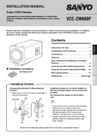
Please read this installation manual carefully in order to ensure correct installation. In addition,
be sure to read carefully the electronic manual contained in the CD-ROM to ensure correct
operation of the camera.
●
Installation accessory
Contents
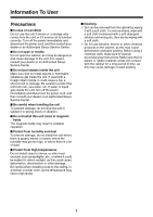
Information To User. . . . . . . . . . . . . . . . . . . . 1
Parts Names and Functions . . . . . . . . . . . . . 3
Connections. . . . . . . . . . . . . . . . . . . . . . . . . . 5
Features . . . . . . . . . . . . . . . . . . . . . . . . . . . . . 7
How to Perform the Settings in the Menu
Screens . . . . . . . . . . . . . . . . . . . . . . . . . . . . . 9
Learning the Menu Setting Operations . . . 10
Using the Electronic Manual (CD-ROM) . . 12
Main specifications . . . . . . . . . . . . . . . . . . . 13
Dimensions . . . . . . . . . . . . . . . . . . Back page
Clamping core
VCC-ZM600P
English
Français
Deutsch
中文简体
Changing the Bracket for Mounting the
Camera
•
Make sure to use the longer screws
(A)
to
secure the bracket.
Install the camera in a correct location so
that the intended object can be monitored
properly.
You should also adjust on the monitor
side.
•
If you want to use a commercially available
platform for the camera, select an
appropriate type, taking into consideration
the gross weight of the camera and
platform, and secure it on a firm place.
•
Images may blur under extremely bright
lighting; adjust the lighting angle to get
clear images.
(B)
(A)
(A)
(B)
✱
Lens cap
Installing Camera
✱
Hole for mounting the camera
(Remove the screw before mounting the camera.)