Sanyo VCC-ZM600N Installation Manual - Page 5
Side panel
 |
View all Sanyo VCC-ZM600N manuals
Add to My Manuals
Save this manual to your list of manuals |
Page 5 highlights
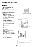
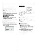
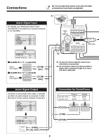
3 System terminals (Push-lock) Used to connect external system control devices. 1 RS-485 control terminals (Push-lock) Used to perform remote operations of the camera. Connect these terminals to a communication device such as system controller. 2 COM terminal (earth terminal) 3 UTP terminals Used to output video signal using a UTP (Unshielded Twist Pair cable). Connect these terminals to the NVT receiver. 4 AC24V/DC12V terminal Inputs the power. Connect this terminal to the power supply. • When the camera is turned on, the POWER lamp lights and the system information of the camera is displayed on the startup screen for about 10 seconds. CAMERA VER PROTOCOL ADDRESS X.XX-XX XXXX X Side panel 1 2 SET b For zoom/focus While viewing the live image, you can perform focusing or zooming operation. 1 c: Wide d: Tele j: Near l: Far 2 Pressing the button once starts auto-focus function. b For menu operations 1 j: Moves the cursor upward. l: Moves the cursor downward. c: Changes the setting value or moves the cursor to the right. d: Changes the setting value or moves the cursor to the left. 2 Pressing and holding the button for about 3 seconds displays the main menu. While performing menu operations, the button may be used to switch the menu screen to the next one. 4
-
 1
1 -
 2
2 -
 3
3 -
 4
4 -
 5
5 -
 6
6 -
 7
7 -
 8
8 -
 9
9 -
 10
10 -
 11
11 -
12
-
13
-
14
-
15
-
16
-
17
-
18
-
19
-
20
-
21
-
22
-
23
-
24
-
25
-
26
-
27
-
28
-
29
-
30
-
31
-
32
-
33
-
34
-
35
-
36
-
37
-
38
-
39
-
40
-
41
-
42
-
43
-
44
-
45
-
46
-
47
-
48
-
49
-
50
-
51
-
52
-
53
-
54
-
55
-
56
 |
 |
