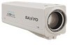
Sanyo VCC-ZM600N Installation Manual - Page 7
Controller, Digital Video, Recorder etc., SYSTEM DEVICE, ex. Monitor
 |
View all Sanyo VCC-ZM600N manuals
Add to My Manuals
Save this manual to your list of manuals |
Page 7 highlights
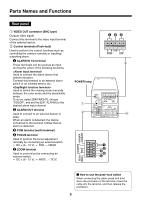
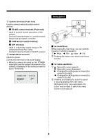
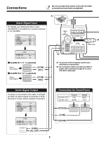
Connection with a communication device for remote operation Controller ✱3 UTP (Unshield Twist Pair) cable: LAN Category 5 or higher ✱3 NVT Digital Video Recorder etc. Receiver SYSTEM DEVICE (ex. Monitor) To output video signal, select the connection of a coaxial cable or a UTP cable. Power Supply Connection b With AC 24 V Monitor Connection GND ~ ~ For the connections, use cables thicker than 18 AWG. b With DC 12 V Check that +/- polarity is correct. - + For the connections, use cables thicker than 18 AWG. • Using different cables from those specified here may attenuate the video and/or sync signals and interfere with correct transmission. • RG-59U coaxial cables can be used when distance between devices is short, but not in duct or aerial routing. Cable type RG-59U (3C-2V) RG-6U (5C-2V) RG-11U (7C-2V) Length 250 m (273 yds) max. 500 m (547 yds) max. 600 m (656 yds) max. Color or Black-and-White Setting The alarm input terminals can also be used as terminals for switching between color and black/white video modes using an external switch. Open: Color Close: Black/White SYNC CAMERA LENS ALARM PRIVACY MASK PASSWORD LANGUAGE OPTION INT 1 y SET y SET y SET y SET y SET y SET y (COM) (ALARM IN 1 or 2) GAMMA MOTION POSITION DAY/NIGHT PRESET MENU 0.45 OFF OFF COLORy OFF BACK Make sure that COLOR is selected. D/N SETTING-COLOR EXT ALARM 1 1: ALARM IN 1 terminal 2: ALARM IN 2 terminal 6
-
 1
1 -
 2
2 -
 3
3 -
 4
4 -
 5
5 -
 6
6 -
 7
7 -
 8
8 -
 9
9 -
 10
10 -
 11
11 -
 12
12 -
13
-
14
-
15
-
16
-
17
-
18
-
19
-
20
-
21
-
22
-
23
-
24
-
25
-
26
-
27
-
28
-
29
-
30
-
31
-
32
-
33
-
34
-
35
-
36
-
37
-
38
-
39
-
40
-
41
-
42
-
43
-
44
-
45
-
46
-
47
-
48
-
49
-
50
-
51
-
52
-
53
-
54
-
55
-
56
 |
 |
