Sanyo VCC-ZM600N Installation Manual - Page 6
Connections
 |
View all Sanyo VCC-ZM600N manuals
Add to My Manuals
Save this manual to your list of manuals |
Page 6 highlights
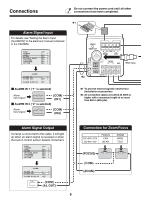
Connections Do not connect the power cord until all other connections have been completed. ✱1 Alarm Signal Input For details, see "Setting the Alarm Input (ALARM IN)" in the electronic manual contained in the CD-ROM. SYNC CAMERA LENS ALARM PRIVACY MASK PASSWORD LANGUAGE OPTION INT 1 y SET y SET y SET y SET y SET y SET y POWER VIDEO OUT A B COM RS485 UTP ALARM IN 2 AC24V GND BNC type ALARM IN 1 ALARM OUT FOCUS COM ZOOM ALARM ALARM IN ALARM OUT ALARM DISPLAY 1 y SET y OFF b ALARM IN 1 ("1" is selected) Alarm input signal (COM) (IN1) b ALARM IN 2 ("2" is selected) Alarm input signal (COM) (IN2) DC12V ✱2 ✱1 To prevent electromagnetic interference (Installation accessories) ✱2 All connection cables should be 24 AWG or higher with a maximum length of no more than 600 m (656 yds). Alarm Signal Output If a lamp is connected to this cable, it will light up when an alarm signal is received or when the built-in motion sensor detects movement. SYNC CAMERA LENS ALARM PRIVACY MASK PASSWORD LANGUAGE OPTION INT 1 y SET y SET y SET y SET y SET y SET y ALARM ALARM IN ALARM OUT ALARM DISPLAY 1 y SET y OFF (COM) (AL OUT) 5 Connection for Zoom/Focus DC+6V/+12V DC-6V/-12V FOCUS FAR NEAR ZOOM WIDE TELE (FOCUS) (COM) (ZOOM)
-
 1
1 -
 2
2 -
 3
3 -
 4
4 -
 5
5 -
 6
6 -
 7
7 -
 8
8 -
 9
9 -
 10
10 -
 11
11 -
 12
12 -
13
-
14
-
15
-
16
-
17
-
18
-
19
-
20
-
21
-
22
-
23
-
24
-
25
-
26
-
27
-
28
-
29
-
30
-
31
-
32
-
33
-
34
-
35
-
36
-
37
-
38
-
39
-
40
-
41
-
42
-
43
-
44
-
45
-
46
-
47
-
48
-
49
-
50
-
51
-
52
-
53
-
54
-
55
-
56
 |
 |
