Seagate ST15150N Product Manual - Page 61
ST15150N/ND/W/WD/WC/DC Product Manual, Rev. D, illustrates ST15150W/WD drives option
 |
View all Seagate ST15150N manuals
Add to My Manuals
Save this manual to your list of manuals |
Page 61 highlights
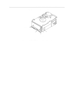
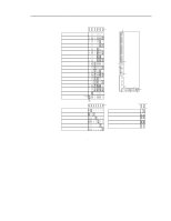
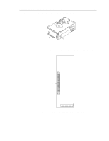
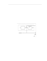
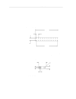
ST15150N/ND/W/WD/WC/DC Product Manual, Rev. D 51 Figure 22 illustrates ST15150W/WD drives option select jumper connectors. J5 SCSI ID = 0 (default) SCSI ID = 1 SCSI ID = 2 SCSI ID = 3 SCSI ID = 4 SCSI ID = 5 SCSI ID = 6 SCSI ID = 7 SCSI ID = 8 SCSI ID = 9 SCSI ID = 10 SCSI ID = 11 SCSI ID = 12 SCSI ID = 13 SCSI ID = 14 SCSI ID = 15 Remote LED Connector Spindle Sync SSREF Cable Connector Pin 1 SCSI Connector Pin 1 J5 Pin 1 Negative (cathode) Positive (anode) Pin 1 Pin 1 Pin 1 Power J4 J01 Connector J4 Enable Drive Terminator* Reserved Parity Disable Enable Motor Start Delay Motor Start Write Protect Pin 1 Pin 3 J01 * Term. power from drive. * Term. power from SCSI bus. Term. power to SCSI bus. * Term. power to SCSI bus and drive. Host adapter or other device provides term. power to external terminator. * Valid for single-ended drives only. Pin 1 Pin 2 Figure 22. ST15150W/WD drives option select jumper connectors
-
 1
1 -
2
-
3
-
4
-
5
-
6
-
7
-
8
-
9
-
10
-
11
-
12
-
13
-
14
-
15
-
16
-
17
-
18
-
19
-
20
-
21
-
22
-
23
-
24
-
25
-
26
-
27
-
28
-
29
-
30
-
31
-
32
-
33
-
34
-
35
-
36
-
37
-
38
-
39
-
40
-
41
-
42
-
43
-
44
-
45
-
46
-
47
-
48
-
49
-
50
-
51
-
52
-
53
-
54
-
55
-
 56
56 -
 57
57 -
 58
58 -
 59
59 -
 60
60 -
 61
61 -
 62
62 -
 63
63 -
 64
64 -
 65
65 -
 66
66 -
67
-
68
-
69
-
70
-
71
-
72
-
73
-
74
-
75
-
76
-
77
-
78
-
79
-
80
-
81
-
82
-
83
-
84
-
85
-
86
-
87
-
88
-
89
-
90
-
91
-
92
-
93
-
94
-
95
-
96
-
97
-
98
-
99
-
100
-
101
-
102
 |
 |
