Seagate ST15150N Product Manual - Page 67
Grounding, Drive termination
 |
View all Seagate ST15150N manuals
Add to My Manuals
Save this manual to your list of manuals |
Page 67 highlights
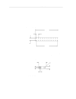
ST15150N/ND/W/WD/WC/DC Product Manual, Rev. D 57 10.3 Grounding Signal ground (PCB) and HDA ground are connected together in the Barracuda 4 family drives-do not separate this connection. Maximizing the conductive contact area between HDA ground and system ground may reduce radiated emissions. A bracket shield with tapped holes is available to system integrators. This shield makes it easier to attach a braid or similar high-frequency grounding device. If you do not want the system chassis to be connected to the HDA/PCB ground, you must provide a nonconductive (electrically isolating) method of mounting the drive in the host equipment; however, this may increase radiated emissions and is the system designer's responsibility. 10.4 Drive termination ST15150N To enable internal drive termination, install a jumper on J01 pins 1 and 2 as shown in Figure 20. ST15150ND You must provide external drive termination when termination is required. ST15150W To enable internal drive termination, install a jumper on J4 pins 11 and 12 as shown in Figure 22. ST15150WD You must provide external drive termination when termination is required. ST15150WC You must provide external drive termination when termination is required. ST15150DC You must provide external drive termination when termination is required.
-
 1
1 -
2
-
3
-
4
-
5
-
6
-
7
-
8
-
9
-
10
-
11
-
12
-
13
-
14
-
15
-
16
-
17
-
18
-
19
-
20
-
21
-
22
-
23
-
24
-
25
-
26
-
27
-
28
-
29
-
30
-
31
-
32
-
33
-
34
-
35
-
36
-
37
-
38
-
39
-
40
-
41
-
42
-
43
-
44
-
45
-
46
-
47
-
48
-
49
-
50
-
51
-
52
-
53
-
54
-
55
-
56
-
57
-
58
-
59
-
60
-
61
-
 62
62 -
 63
63 -
 64
64 -
 65
65 -
 66
66 -
 67
67 -
 68
68 -
 69
69 -
 70
70 -
 71
71 -
 72
72 -
73
-
74
-
75
-
76
-
77
-
78
-
79
-
80
-
81
-
82
-
83
-
84
-
85
-
86
-
87
-
88
-
89
-
90
-
91
-
92
-
93
-
94
-
95
-
96
-
97
-
98
-
99
-
100
-
101
-
102
 |
 |
