Seagate ST15150N Product Manual - Page 66
ST15150W/WD
 |
View all Seagate ST15150N manuals
Add to My Manuals
Save this manual to your list of manuals |
Page 66 highlights
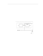
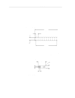
56 10.2.1.2 10.2.1.3 ST15150N/ND/W/WD/WC/DC Product Manual, Rev. D Termination The reference index signal (SSREF+) is terminated with a 2.21K ohm resistor. Each single-ended drive has a terminator resistor located on the main PCB. The terminator resistor is not removable and is always in the circuit. A diode prevents current from backfeeding. Physical interface Dimensions of the J04 (J4) connector mounted on the main PCB of ST15150N/ND drives to interconnect the drives are shown in Figure 26. The connector is a 22-pin, 11-position gold 2 mm header type. Only pins 1 and 2 are used for connecting the reference index signal cable, as shown in Figure 20. Pin 1 is SSREF+ and pin 2 is ground. .866 (22 mm) .079 (2 mm) .079 (2 mm) J04 .787 (20 mm) Figure 26. ST15150N/ND drives configuration select header specification Dimensions of the J5 connector mounted on the main PCB ofST15150W/WD drives to interconnect the drives are shown in Figure 27. The connector is a 12-pin, 6-position gold 2 mm header type connector. Only pins 11 and 12 are used for connecting the reference index signal cable, as shown in Figure 22. Pin 11 is SSREF+ and pin 12 is ground. .079 (2 mm) .520 (13.2 mm) J5 .079 (2 mm) Pin 1 .185 (4.7 mm) Figure 27. ST15150W/WD drives configuration select header specification
-
 1
1 -
2
-
3
-
4
-
5
-
6
-
7
-
8
-
9
-
10
-
11
-
12
-
13
-
14
-
15
-
16
-
17
-
18
-
19
-
20
-
21
-
22
-
23
-
24
-
25
-
26
-
27
-
28
-
29
-
30
-
31
-
32
-
33
-
34
-
35
-
36
-
37
-
38
-
39
-
40
-
41
-
42
-
43
-
44
-
45
-
46
-
47
-
48
-
49
-
50
-
51
-
52
-
53
-
54
-
55
-
56
-
57
-
58
-
59
-
60
-
 61
61 -
 62
62 -
 63
63 -
 64
64 -
 65
65 -
 66
66 -
 67
67 -
 68
68 -
 69
69 -
 70
70 -
 71
71 -
72
-
73
-
74
-
75
-
76
-
77
-
78
-
79
-
80
-
81
-
82
-
83
-
84
-
85
-
86
-
87
-
88
-
89
-
90
-
91
-
92
-
93
-
94
-
95
-
96
-
97
-
98
-
99
-
100
-
101
-
102
 |
 |
